A Guide to Creating an Electrical Drawing
Elecdes provides many symbols and functions for creating electrical drawings.
This guide is intended to show you the recommended procedure for creating a drawing. When you are comfortable with the basic procedure, refer to the How to sections and Reference sections for assistance with the advanced features of Elecdes.
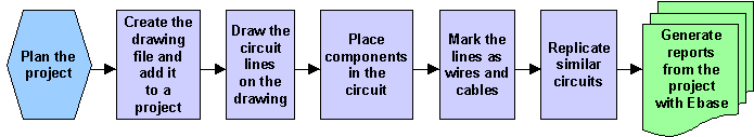
Plan the Project
Plan a suitable directory structure for the drawings that you are going to produce for a project. The recommended procedure is to arrange your directories to represent your plant layout.
Decide upon the types of drawings required and the numbers of each type. I.e. do you need a block diagram or several one line diagrams? Will you place your control circuit diagrams on separate sheets to your 3 phase circuits or will each motor be modular? Is the use of Protogen an option due to the repetitive nature of your circuits? Do you need wiring diagrams produced after the schematics are created? Is component specification necessary and if so to what level? Ensure that your catalog's will allow you to achieve this level so that your reports and cross-references are output as expected.
For large projects, we recommend that a DIAGRAM be drawn, showing your project organisation.
Ensure EDS is configured to the correct units: metric or imperial with the Setup program. Choose the component naming style that you require in the Naming Sequencer. Choose the menu files and catalog files that will be available.
Create the drawing file and add it to an Elecdes project
Create a new drawing.
Typically you will use "File->New" or "File->SaveAs" within the CAD session to create a new DWG file for a circuit. Protogen can also be used to create new DWG files for your circuits.
New drawings can be created from your own templates or from the templates supplied with your CAD package. Save the new drawing in the appropriate directory for this part of your design. Many Elecdes functions require the drawing to be named.
Many Elecdes functions require that the drawing is part of an Elecdes Project. You should create a "project" (project definition file) before you commence drawing. The project definition file contains the list of DWG files of the project and it also contains project-related settings. The project definition file allows the full functionality of Elecdes to be available immediately.
Add the drawing to the Elecdes Project.
Place a border on the drawing. You can use your own borders. Sample border files are supplied with EDS and with your CAD package.
Draw the circuit lines on the drawing
Many circuit types should be started by drawing the lines to represent the conductors. Components are then inserted onto the conductors. Ladder control schematics and single line drawings are good examples of where the conductors are drawn prior to components being inserted.
LINE entities and ARC entities are used to represent the conductors on Elecdes schematics.
Three phase schematics and instrument loop diagrams are best constructed using automated drawing functions (also known as macros) that repetitively place multiple lines and components onto the circuit. Refer to the How to sections for assistance when using the automated drawing functions.
Hint: ORTHO ON and SNAP ON are two very useful CAD package tools for ensuring all of your wire lines are perfectly spaced and connected. Elecdes turns ORTHO ON when a new drawing is created and sets the SNAP by way of a MET_SNAP/IMP_SNAP setting in the EL32.INI file. We do not however recommend the use of OBJECT SNAP for any electrical drawing as it encourages random spacing and lines which are off the horizontal and vertical plane.
Place components in the circuit
Place symbols to represent components (fuses, terminals etc.) onto the lines of the circuit. The Elecdes functions that insert symbols will align the symbol with the lines of the circuit and break the lines to fit the symbol.
Functions are provided to copy, move and delete symbols and also to repair any line breaks that remain, after a symbol is deleted.
Mark the lines as wires and cables
Any LINE entities that logically connect to a device or terminal are considered, by Elecdes, to represent a conductor. You can assign a name and specification to that conductor and identify it as either a single cable core(conductor), wire, or a multi-core cable.
Place wire or cable core(conductor) markers on the line segments to assign conductor names and specifications.
Wire and cable core(conductor) markers can be placed individually on lines. Wire markers can also be placed automatically on a user-selected group of lines.
Replicate similar circuits
If you are about to create multiple circuits that are similar, then you should not draw each circuit individually. Draw the first circuit completely using the steps outlined above. For a circuit that is one of many parts of a single DWG, you can use the copy command from your CAD package to make copies of the circuit.
Use the Elecdes Update function to modify the names and specs. of the components in each copy of the original circuit. The Update function runs the Global Editor to modify component data.
If you have entire drawings that are similar, you can copy a drawing and use the Ebase Global Editor to modify the components in each copied drawing.
Generate reports from the project with Ebase
You can use the reporting module Ebase to generate the Bill of Materials report, Connection reports and Cross-Reference report for the project. Ebase can place coil and contact cross-reference information on each drawing in the project.