PLC Wizard
The PLC Wizard I/O card generator function will construct an IO card from; a library of PLC channel (input/output/common) symbols, a catalog entry which defines the card and several user construction options. Cards can be drawn with wiring on either side. Cards can be drawn with horizontal orientation or vertical orientation. Cards may be split into 2 or more sections to accommodate sheet size.
When a card is created a series of "IO wiring macro" symbols will be attached to the IO channels of the card. These IO macros contain intelligent wiring, terminals and devices. The IO macros represent the marshalling and field IO components of the circuit for a single input / output.
The generation of PLC cards allows considerable flexibility in the layout and look of the cards. The symbols used to create the card may be modified by the user to their own desired "look". The symbols can have the following changes: size, spacing, fonts, colours, layers, line types. (You can redraw the symbols completely!) The wiring macros may also be altered extensively. New USER wiring macros can easily be created.
PLC IO Card Generation
PLC Wizard can be run as standalone application from its shortcut in the EDS program group, or from Elecdes.
The standalone application can only create and edit PLC IO Card configurations, and must be run from inside Elecdes to construct a card on a drawing.
The PLC generation process is done in 4 stages:
Note: If you are using Instrument Manager you will be defining the card only (not the wiring and IO components) and therefore Stage 1 only applies.
Procedure (Standalone)
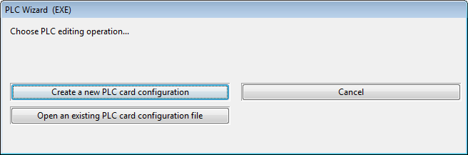
Start PLC Wizard. The following menu will be shown:
-
You may create a new PLC card configuration, or open an existing configuration.
If you choose to open an existing configuration, navigate to and select the configuration file (DBF) for the card you want.
The PLC Wizard will start. If you opened an existing configuration, the settings will be loaded into the wizard, otherwise, default values will be used.
The Wizard has two stages to complete:
You can freely switch between the two stages by clicking and
You can also access preferences by clicking
Once you have completed configuration of the PLC IO card, click Finish on the stage 2 page, and save the PLC configuration file.
To construct the PLC IO card in an Elecdes drawing, you now need to run PLC Wizard from Elecdes, then click and select the PLC configuration file (DBF) you saved in the previous step.
Then follow the Construction instructions.
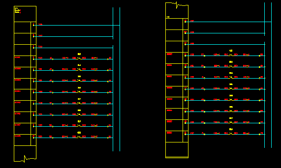
Example
A card generated vertically in two parts