How to Automatically Name Wires in a Drawing
Fundamentals
The Elecdes wire placement function can automatically place wire marker symbols onto a group selection of conductors. Wire markers will only be placed upon conductors that do not already have wire or cable core (conductor) markers attached.
The Auto-wire function will start if; you are executing the normal wire insert function and you are being requested to "pick an insert point" and you pick a point that is not on a line segment.
Once the Auto-wire function has started, you may then pick a second point, defining a rectangular area, within which, wire markers will be assigned to all unnamed conductors.
When assigning the unallocated wire names, the Auto-wire function will check all of the wire names used in your current Elecdes project. You should ensure that the project contains all of the drawings that contain wire markers.
Procedure
-
Select from the menu.
-
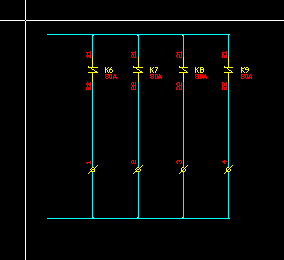
Pick a point to the top-left of the wires that will require naming.
Ensure that the point is not over a line segment, otherwise it will insert the wire marker as in the standard insertion procedure.
-
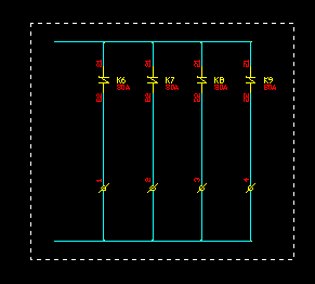
Pick the second corner of the area encompassing all of the wires that will require naming.
-
You will be asked if you want to save the drawing. This is required so that the conductor information can be extracted from the saved drawing file. If you choose not to save the drawing then the Auto-wire function will terminate.
-
If the drawing is not in the current project then you will be offered the option to add it to the current project. If you do not add the drawing, the function will terminate.
-
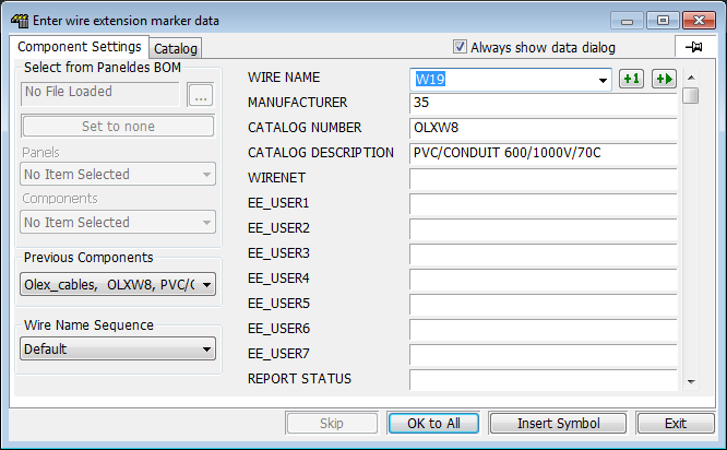
For the first wire marker you will need to enter the attribute data into the Elecdes Component Dialog, as required during the standard insertion procedure. The name of the wire will be incremented in the sequence configured by the Naming Sequencer. The chosen catalog specification will be used for all of the wires that are placed.
-
When you are satisfied with the data in the Component Dialog for the first wire, click the Insert Symbol button.
-
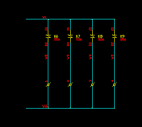
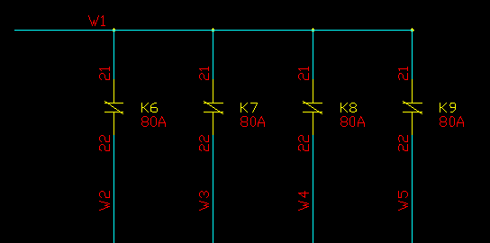
Wire markers will be attached to the longest line segment from each set of line segments that represents a distinct equipotential or conductor.
Any line segment that crosses the specified region will be included in the set to be auto wired.
Any zone that overlaps the specified region will be added, in its entirety, to the region to be auto wired. Line segments within zones will be auto-wired before line segments that are not within zones.
-
The standard wire placement function will now continue, as it does during the standard insertion procedure.