How to Insert Symbols
Fundamentals
Most Elecdes symbols are inserted using the same general procedure.
The following is an outline of the usual steps required to insert a symbol:
-
Choose the symbol type.
-
Pick the location on the drawing where the symbol will be placed.
-
Enter the name, location and any other data that is entered manually per symbol.
-
Select a specification for the component from the catalog.
-
For subcomponents of a component already in the drawing, choose the available specification from the supplied list.
-
The symbol is inserted.
Procedure
-
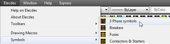
Display the appropriate icon menu of symbols.
The various icon menus can be selected from the menu. Wire and cable core (conductor) markers can be selected from the menu. These icon menus can also be found upon the relevant Elecdes toolbars.
-
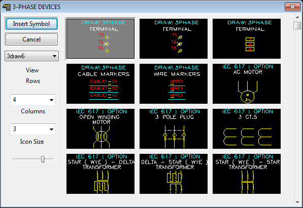
Select the symbol by clicking on the desired icon for device, terminal and instrument symbols.
Wire and cable core (conductor) markers do not require an icon menu as each function on the menu inserts a single type of conductor marker.
-
If you have pinned the component attribute dialog then it will become active so that you can enter attribute data for the component. If you have previously closed the dialog then it will be re-displayed.
-
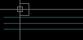
You must then select the insert point.
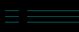
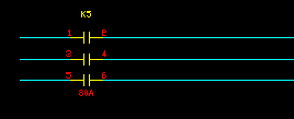
Insert points, for symbols "broken in" to conductors, should be placed upon an Elecdes horizontal or vertical line segment. If you are inserting into two lines, then select the UPPER or LEFT line. If you are inserting into 3 lines, then select the CENTRE line.
For device and terminal symbols, a "Soft Snap" cursor box is provided. This displays, with the cursor, a surrounding box representing the size and orientation of the symbol or symbols to insert. The orientation will "lock" or "snap" to any line segment it detects, altering the orientation as required.
If you do not wish to insert the symbol on a line or lines, you may use the "TAB" key to change orientation.
NOTE: Elecdes component symbols will not work correctly for Ebase reports if they are rotated by CAD commands. You should instead use the H or V prefixed symbol that is appropriate to the conductor lines in the circuit in which it is placed.
NOTE: Symbols or whole drawings can be scaled once placed but Elecdes does not offer to scale symbols during insertion.
The next tagname, current panel number and last catalog number are shown on the command line prompt.

For most symbols you may press M, at this stage, to pick multiple lines on which to insert multiple symbols. See How to insert symbols onto multiple lines in one operation.
Press A to display the component attribute dialog if it is not currently displayed (e.g. if it was pinned but subsequently closed, or if you have chosen to not show the attribute dialog).
Press Z to turn on ZoneTag mode, which will detect zones and lines under the cross-hair and adjust the component name if necessary.
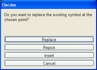
If the selected insertion location already contains an Elecdes symbol then you will be presented with the option to replace the existing symbol with the one you are currently inserting.
Alternatively you can choose to select a different insertion point, or to insert the new symbol and leave the previous symbol as is.
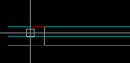
-
For device and terminal symbols, Elecdes will break the line or lines to fit the symbol.
-
Symbols without attributes, such as reference and indicator symbols, will simply request an orientation and will then be inserted. If the reference and indicator symbol is not named or found then Elecdes will allow you to browse for a symbol to insert.
-
The Elecdes Component Dialog will be displayed.
Elecdes Component Dialog
-
You should enter the name, location and any other data that needs to be manually entered (e.g. visible description) into the edit boxes to the right. Manually entered data is that which usually varies for every component e.g. a component's tag name or function (visible description)
Any preset attributes that you have set in your menu entry or within the symbol file will contain the specified preset value.
The Naming Sequencer will have supplied defaults for the naming attributes (tagname etc.).
The naming sequencer can build your tagnames using the following drawing based data; the name of a ZONE to which you inserted the symbol, the name of the current LAYER, the name of the layer of the line (LINELAYER) you inserted on to, the sheet name or PAGE you have entered in your titleblock.
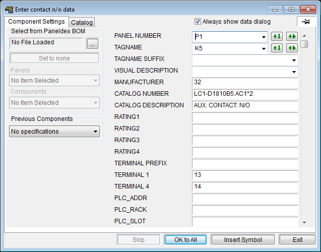
The checkbox Always show data dialog gives you an option for whether the component insertion dialog will be shown. The option to show the dialog is saved independently for each type of symbol (e.g. Devices, Terminals, etc.) that you can insert. If you untick this option then the dialog will not be shown while you are inserting components, however you can show the dialog when desired by entering the keyword ATTRIBUTES or simply pressing A then Enter at the command line.
You can change the default for whether the dialog will be shown or hidden and you can clear any choice made on the dialog to either show or hide the dialog for a type of symbol. See How to Show or Hide the Symbol Data Dialog.
If you press the PIN
 button, then the dialog will be PINNED to the screen so that it is always visible. Pinning to the screen gives you the freedom to insert the symbols without interacting with the component dialog, yet the dialog remains immediately available if you need to change any attribute values.
While the dialog is pinned, the tagname will be updated as you roll your mouse over different ZONES and LINES if you activate the [Zonetag] option by entering the keyword ZONETAG or simply pressing Z then Enter at the command line.
Click the
 button next to the PANEL NUMBER to increment the panel number by one (e.g. from P1 to P2).
Click the
 button next to the PANEL NUMBER to increment to the next available panel number in your project.
Erase the current panel number then click the
button to get the first available panel number in your project.Click the
button next to the TAGNAME to increment the tagname by one (e.g. from K1 to K2).Click the
button next to the TAGNAME to increment to the next available tagname in your project.Erase the current tagname then click the
button to get the first available tagname in your project.-
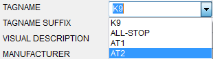
Some of the attributes have drop down lists from which you can select from a list of names, locations etc. These lists are loaded from any components previously inserted into the current project.
-
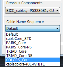
For wire and cable-core (conductor) markers, which have a variety of naming styles, you can choose one of the available name sequences from a drop-down list in the bottom left corner under the selection of previous components. Choosing a new sequence from this list will re-set the wire or core (conductor) name attribute on the right side of the dialog to next value in the chosen sequence. This choice is linked to the same choice in the Elecdes preferences. See How to Configure Cable and Wire Naming Sequences.
-
The order that the symbol attributes are displayed on the Elecdes Component Dialog can be changed. See Changing the Attribute Order During Symbol Insertion.
-
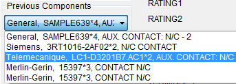
At the bottom left of the dialog is a drop down list that will contain the last five specifications that you have selected for this type of component. You may select one of these specifications by picking in the list.
-
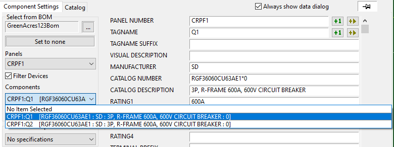
On left of the dialog is a group of controls to enable you to select a component from a Paneldes or Elecdes BOM file. Click on the button to load a BOM file.
Pick the panel, then pick a component entry from that panel. Elecdes will use the specification, from the catalog, associated with the manufacturer code and catalog number obtained from the chosen entry.
For subsequent insertions of the same type of component, Elecdes will default to the next component in the list from the BOM. To use the entry from the list that is currently displayed, click the button .
Elecdes will offer you the components from the BOM based device that match the symbol you have previously selected. For example if you have selected a normally open contact to insert then the BOM list will offer you only the normally open contacts of a relay from the BOM. If the component in the BOM has no matching components then you will be offered the "0" or "primary" subcomponent of the part number by default.
If you have a requirement to choose a catalog specification that does not match the block type, untick the box Filter Devices.
-
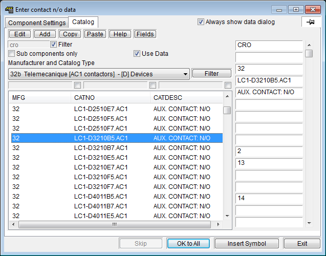
Click on the Catalog tab at the top of the Component Dialog in order to view a list of component specifications from the manufacturer's catalog's.
Select a manufacturer and specification for your component.
-
When you are satisfied with the data in the Component Dialog, click the Insert Symbol button.
-
If you are performing a multi-insert and do not wish to be prompted for attribute information for each of symbols you can click instead of . The name for each component will automatically be incremented by the name sequencer.
-
Elecdes will perform an On-Line Cross-Reference for the component.
If the component or part of the component has already been placed upon a drawing in the project or if you enter a cable core (conductor) name that is incorrect for the type of cable, then you will be shown a list of references to any related parts using your component's tagname. See On-Line Cross-Reference for more information.
During project component scans there is a possibility that the database engine will be busy. You will be shown a message indicating this and given options to wait or cancel.
-
The data will be placed in the attributes of the component, which will then be inserted.
-
If you are inserting one of the conductor marker symbols (wire, cable core (conductor) etc) the function will repeat now. You may continue to place multiple conductor markers. Press ESC to exit the loop.
See also
How to insert components directly from the catalog.
How to insert a subcomponent from an existing relay.
How to insert symbols onto multiple lines in one operation.
How to insert an array of symbols
How to select a component from the on-line tag check list.
How to insert a Multi-Terminal Device symbol.
How to align an instrument tag symbol with a terminal.
How to connect to equipment that is not in the project
How to insert a NC contact when the catalog specifies NO
How to insert a block that is already used in the drawing
How to repeat the last symbol insertion.
How to repeat a recent icon menu insertion.
There are many preferences that control symbol insertion. Elecdes can redefine a symbol during insertion.