How to Insert Symbols Onto Multiple Lines in One Operation
Fundamentals
The option of inserting MULTIPLE symbols is available for most symbols. This can be recognised by the prompt <Multiple> appearing on the command line, during an insert point request.
You also have the option of inserting an ARRAY of Elecdes symbols. See the Symbol Array discussion in the next section.
Procedure
-
Begin the insertion procedure as detailed in the previous section.
-
When asked to pick the insertion point of the symbol, press ENTER.
-
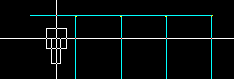
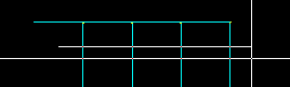
You will be asked to pick two points defining the endpoints of the "line of multiple insertions".
Ensure the ORTHO setting is ON in the CAD for best results
-
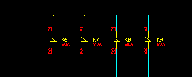
A symbol can be inserted at each point where the "line of multiple insertions" crosses a conductor on the drawing. For multiple insertions you have the option to skip one or more of the conductors. This can be done by clicking the [Skip] button on the Elecdes Component Dialog.
-
For each symbol you will need to confirm the attribute data for the component within the Elecdes Component Dialog, as done in the standard insertion procedure. The name of the symbol will be incremented in the sequence configured by the Naming Sequencer.
You can also confirm the attributes for just the first symbol and then click the [Ok to All] button on the Elecdes Component Dialog. This will insert all of the symbols required using the names defined by the sequence configured by the Naming Sequencer.