A Guide to Constructing a General Arrangement Drawing
Introduction
Paneldes allows you to construct a dimensioned general arrangement drawing of your panel plates and mounted components.
Constructing a General Arrangement Drawing
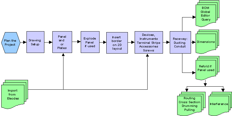
Procedure
-
Produce a summarised sketch of the panel and components including approximate positions, possibly including a list of components.
-
Produce a set of specifications for the components you are about to place in the system.
-
Set up your drawing scales and insert a border and view ports. See Starting a New Drawing, Model Units and Scaling, Inserting Borders, Inserting Viewports.
-
Insert a panel into the model. Add any additional plates to the panel. See Placing Panels and Placing Plates. Explode the panel into 2D. All the plates will be exploded out and you will be transferred to the General Arrangement layout. See Exploding a Panel.
-
If you wish to use a single plate instead of a panel, place the plate directly into the empty drawing. See Placing Plates.
-
If you have exploded a panel, insert a border on the General Arrangement layout tab. See Inserting Borders.
-
Mount any devices and instruments, accessories and terminal strips, on the plate(s). See Placing Devices and Instruments, Placing Accessories, Placing Terminal Strips, Placing Accessories and Placing Screws.
-
Place ducting and conduit required into the model (mounted on plates or linking plates). See Placing Raceway.
-
You can now generate a Bill of Materials, use the Global Editor to modify components and the Query tool to check component data. See Generating a Bill of Materials, Global Editing, Querying Components.
-
You can dimension the plates and position of components on the plates. See Dimensioning Plates.
-
If you have exploded a panel, then you can now rebuild it into 3D. See Rebuilding a Panel.
-
Once you have rebuilt the panel into 3D you can perform the following operations.
-
Run wire harness optimisation functions (re-order terminations for optimal looping, establish wire lengths and ensure ducting is sufficient). See Wire Routing.
-
Check for interference between components in your model. See Checking for Interference.
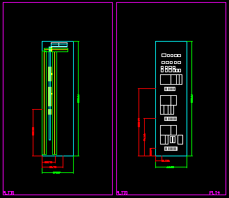
The picture below shows an example of a general arrangement drawing produced by Paneldes.