How to Place an Accessory
Procedure
-
If you want to place an accessory that is visible on the drawing choose the Place Accessory entry from the Construction menu.
-
If however, you want to place an Accessory that only appears as a dot on your drawing but will appear in the Paneldes bill of materials, you should choose the Place Inv. Accessory entry from the Construction menu.
-
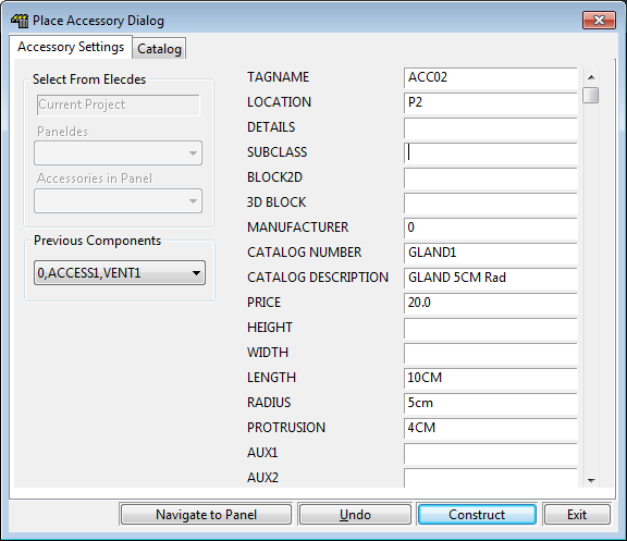
The set of data fields on the right of the dialog box contains the information about the accessory that you are going to insert. You can manually enter data into these fields or click on the Catalog tab at the top of the dialog to pick an accessory from a catalog. For an explanation of each of the fields for an accessory, see the Accessory Attributes reference item.
-
On the left side of the dialog you will see the Previous Components list. To learn more about how to use this, see the Using Previous Components reference item.
-
If you have an Elecdes bill of materials, you can import accessories from it into Paneldes.
To learn more about this, see the Using Components from Elecdes reference item.
-
If you want Paneldes to make the panel you have chosen for the location of the accessory visible in AutoCAD, click the Navigate to Panel button.
-
-
If you want to insert a Gland, ensure that the SUBCLASS is set to GLAND. A catalog specification should set this correctly.
If you want to insert a Routing Termination Point, ensure that the SUBCLASS is set to TERMPOINT. Routing termination points are control entities for routing so they do not usually have a catalog specification.
You must ensure to set the SUBCLASS of these accessories as they are inserted because you cannot change SUBCLASS later in Global Editor.
-
Once you think you have provided sufficient information to construct the accessory, click on the Construct button. If you have not entered sufficient information for Paneldes to construct your accessory you will be warned that one or more parameters are missing.
You may also be warned that an accessory with the same tagname and location as the one you are about to place already exists on the drawing. You may duplicate the component but it is not recommended to do so.
Once you have fixed any problems, click construct again. The dialog will disappear and you will be asked to pick the position for the accessory on the AutoCAD command line. You will also notice that the cursor will be showing you a white box representing the outline of the accessory.
-
For a full description of all the available options when placing a Paneldes object, see the Placing Paneldes Objects reference.
-
Once you have chosen the position and orientation for the accessory, you can either, click the left mouse button or type in the position on the command line as a 3D point and push enter. The accessory will be constructed and you will be returned to the Place Accessory Dialog, ready to place another accessory.
-
If you want to undo the last device you have constructed, click on the Undo button, Your drawing will be restored to the state it was in, prior to you constructing the device. This button is equivalent to the AutoCAD undo command.
-
To exit without constructing another accessory, click on the Exit button or close with the X in the corner of the window.
Glands and Routing Termination Points
Glands and Routing Termination Points are specific recognised SUBCLASS types of the ACCESSORY class. These accessories affect the termination of a cable at a panel.
How to use Glands to Define the Entry Point to a Panel
How to Define a Specific Termination Point for a Cable Inside a Panel