How to Place Raceway
Procedure
-
To place a segment of ducting or raceway you need to use the entry in the Construction menu.
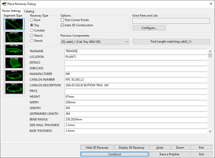
The Place Raceway dialog will be shown:
-
The set of data fields on the right of the dialog box contains the information about the segment of raceway that you are going to insert. You can manually enter data into these fields or click on the tab at the top of the dialog to pick a raceway segment from a catalog.
For an explanation of each of the fields for a raceway segment, see the Raceway Attributes reference item.
-
Above the data fields is the Previous Components list.
-
-
Choose the type of raceway you want to construct from the group.
-
Choose the shape of the raceway segment to place from the pictures in the group.
-
Configure the raceway options checkboxes:
-
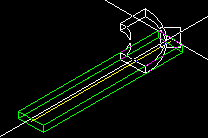
Trim Corner Points
This means that when you attach a corner to a length or attach a length to a corner, Paneldes will trim an amount off the length you pick, so that the length you pick is measured from the centre of the corner. This also applies when attaching a length to Risers, T-Sections and X-Sections and vice versa. An example of this is shown below. Here a corner is being attached to a length. The corner has trimmed the length.
-
Auto 3D Construction
If this option is ticked, Paneldes will automatically generate the 3D envelope for the segment when it has been placed.
-
-
Optionally, configure a lid for the raceway segment, as well as any extra parts, using the Extra Parts editor.
You can now use the utility function buttons at the bottom of the dialog.
-
You can zoom and pan around the drawing using the and buttons.
-
You can display and hide the 3D raceway envelope by using the and buttons.
-
If you want to undo the last raceway segment you have constructed then click . Your drawing will be restored to the state it was in, prior to you constructing the raceway segment. This button is equivalent to the AutoCAD undo command.
You can now construct the segment of raceway, or trace a center line with several segments of raceway.
Construction
If you think you have provided sufficient information to construct the raceway segment, click on the button.
If you have not entered sufficient information for Paneldes to construct your raceway segment, you will be warned that one or more parameters are missing.
You may also be warned that a raceway segment with the same tagname as the one you are about to place, already exists on the drawing. You may duplicate the tagname but it is not recommended to do so as it will cause problems when you come to generate wire and cable routes.
Once you have fixed any problems, click construct again.
The dialog will disappear and you will be asked to pick the position for the raceway segment on the AutoCAD command line. You will also notice that the cursor will be showing you a white box representing the outline of the raceway segment you are about to insert.
For a full description of all the available options when placing a Paneldes object, see the Placing Paneldes Objects reference.
Tracing a 3D Center Line
You can trace a 3D center line (3D POLYLINE entity) with several segments of raceway with the button. The tracing will use the 3D polyline and the raceway specification data you have chosen.
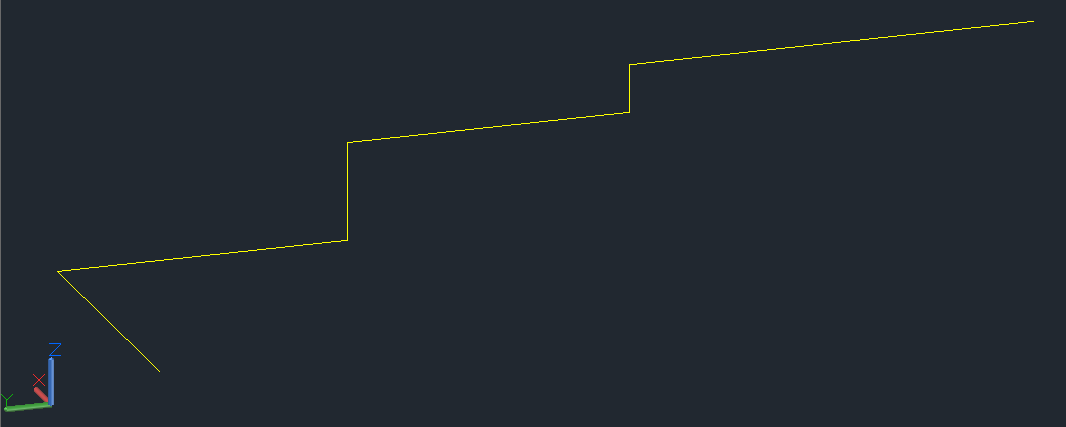
Step 1: Draw A 3D PolyLine
The first step is to draw a 3D POLYLINE with Autocad on your model. This polyline must be constructed with the 3DPOLY command. The trace function can only construct raceway segments with 2 ends therefore you must add junctions (TEES and Xs) later.
Tips:
The 3DPOLY command can be used in conjunction with ORTHO to sketch a 3D center line for your tray. With ORTHO ON the sketch will truly produce a 3D sketch. With ORTHO OFF the line produced will be limited to the current UCS 2D XY PLANE (not very useful!).
Start the sketch with a horizontal tray whenevey possible, as a vertical tray can provide an ambiguous "top of tray" orientation at its start point.
The 3DPOLY command can be used in conjunction with OBJECT SNAP to form a center line for your tray or conduit.
Try to only construct corners in 1 plane at a time. It is difficult to purchase a RISER/CORNER hybrid tray section.
The Paneldes preferences pages contain a setting for the Polyline tracing maximum corner angle that will be treated as a curved corner. If your corner exceeds this angle then 2 linear segments will be created, connected to eachother, without a curved corner/riser. The setting is found on the General page of Paneldes Preferences.
Step 2: Input raceway specification and bend radius
The second step is to fill in the Place Raceway dialog as described at the top of the page.
The specification should be selected from the catalog or entered for a LINEAR SEGMENT of raceway. The linear segment dimensions are expected by the tracer.
You MUST also add a BEND RADIUS value for the tracer to use with corners and risers being constructed. Note that LINEAR SEGMENTS do not usually have a BEND RADIUS value.
Once you think you have provided sufficient information to construct a LINEAR raceway segment, click .
Tips:
The first raceway segment name will be composed of the tagname in the dialog (e.g. "TRAY1") with a suffix (e.g. ".1") added (e.g. "TRAY1.1") This suffix increments as each segment of raceway is added along your 3d polyline. (e.g."TRAY1.1" "TRAY1.2" "TRAY1.3" etc.). You can change the delimiter that comes before the suffix: see Conduit run delimiter in How to Configure the Wire and Cable Routing Settings.
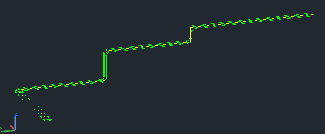
Step 3: Choose the 3D POLYLINE to trace
The final step is to choose the 3D polyline to trace.
Select one or more 3D POLYLINE entities and they will be constructed.
See also
How to tune your model for wire and cable routing