Card Specification
Previous/Next stages
Define the CARD and choose wiring macros for the IO channels
Stage 1: PLC/DCS Card Specification
Define the CARD and choose wiring macros for the IO's
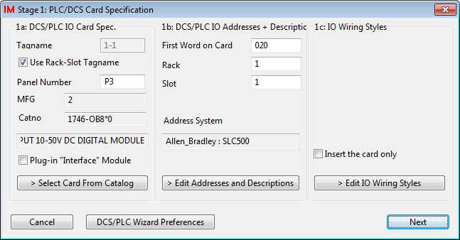
Step 1a: PLC IO Card Spec
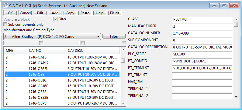
Before any other steps you should decide upon your IO card type. Defining the IO card type includes selecting it from the catalog to get its IO definition and naming system. Click in the section of the dialog.
Following catalog selection, a tag name and panel number should be entered for the card.
Step 1b: PLC IO Addresses and Descriptions
Information such as "First Word", "Rack" and "Slot Number" are usually helpful in your PLC diagrams/documentation and can be used in the PLC Wizard's automated address generation program (for some PLCs). You should enter this information to the section of the dialog.
From the Catalog information, first word, rack and slot, the programmable address generator can generate the addressing for the inputs and outputs of the card. These addresses need not be final. It is possible to edit them by clicking , which will display the Address Definition dialog shown below.
Address Definition dialog
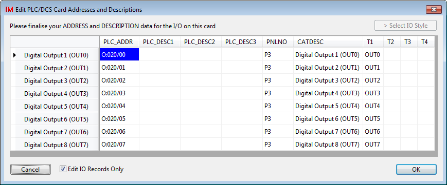
As the name implies, this is also the point when you can enter up to 3 lines of functional description for each IO channel.
The PLC_ADDR column contains the addresses.
The PLC_DESC1, PLC_DESC2, PLC_DESC3 columns are available for the IO channel functional descriptions.
Hints: Use the right menu to access fast editing options in the Address Dialog. Cut and paste from external applications (such as PLC programming packages) is possible at this point for addressing and/or descriptions.
Step 1c: IO Wiring Styles
The button, in the section, enables you to change individually the IO macro options that have been set for your cards IOs.
If you want to omit the wiring from the drawing, then you can check the tick box. This will prevent the wiring from being drawn with the card. The card is inserted by itself, much like inserting an elongated device symbol. You can draw the wiring manually after the card is constructed. See also Single IO Point in the Construction step.
Wiring Style dialog
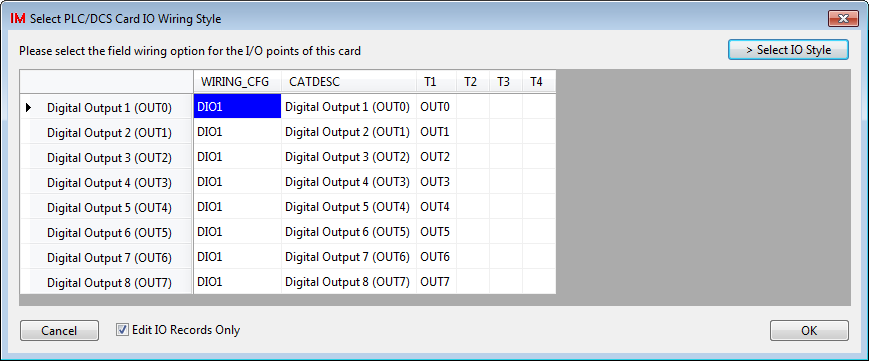
On the Wiring Style Dialog, the WIRING_CFG column contains the PLC Wizard's definition of the wiring macro for each IO channel. Prior to your editing, PLC Wizard will make a default choice from a selection of its standard wiring macros and fill this column with those selections. You may highlight any macros that you wish to change and use the button to select a replacement for those highlighted.
When a "user" wiring macro is selected within PLC Wizard, the complete file name is stored in the WIRING_CFG column e.g. MACRO_VPLC_USER_MY01M. This file name is orientation specific and will not rotate if you later choose a card orientation that does not suit. Therefore choose the correctly oriented macro if choosing by file name.
If a "standard" wiring macro is chosen within the PLC Wizard, an abbreviated name is stored. This name is not orientation specific and PLC Wizard can adjust the actual file name to suit any card orientation you choose.
The Select IO Style dialog
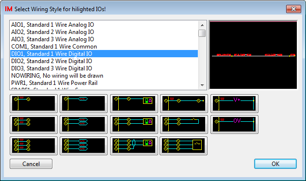
On the Select IO Style Dialog you can select the wiring macro to use from a list on the left side OR select it from an array of buttons underneath the list. The item you highlight will show a preview on the right side of the dialog.
The picture buttons, that are positioned beneath the list, can be used to select any of the standard wiring macros supplied with PLC Wizard.
Next Stage
After selection of your IO wiring macros, click to continue to stage 2.