Construction
Previous/Next stages
Define the CARD and choose wiring macros for the IO channels
Define the orientation and "splitting" for the card
Position the Card on the sheet and construct
Stage 3: Define the orientation and "splitting" for the card
This step can only be started by clicking when runing PLC Wizard from Elecdes.
You will then be prompted to load a PLC configuration file (that was saved at the end of stage 2, or was created/modified manually with DBF Editor).
After selecting a valid configuration file, the Construction Options dialog will be shown:
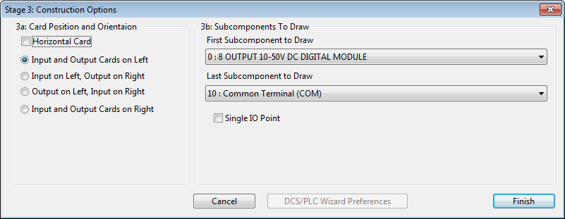
The Graphical Options dialog is divided into 2 areas.
Area 3a: Card Position and Orientation
Area 3b: Subcomponents to Draw – Card Spitting.
These options typically change the way the card is constructed.
3a: Card Position and Orientation
The card position and orientation settings allow you to rotate your card and force IO wiring to be on either side of the card for inputs and / or outputs.
You must ensure that any USER wiring macros that have been selected match the card orientation and wiring side selected!
This following table describes the Orientation settings that can be changed in Area 3a:
| Setting Name | Description |
|---|---|
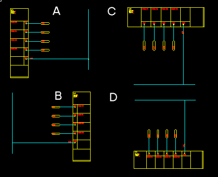
| Horizontal Card | Orientation of the card – Cards C+D below are horizontal. Cards A + B are vertical. |
| Input Cards on Left / Top | Cards with at least one INPUT channel will be drawn on the Left (A) or Top (C). |
| Output Cards on Left / Top | Cards with NO INPUT channels will be drawn on the Left (A) or Top (C). |
| Input Cards on Right / Bottom | Cards with at least one INPUT channel will be drawn on the Right (B) or Bottom (D). |
| Output Cards on Right / Bottom | Cards with NO INPUT channels will be drawn on the Right (B) or Bottom (D) |
Card Orientation Options
3b: Card Splitting
If a card is too large to fit on a single sheet you may split it into several parts. Use the option to split the card.
The two subcomponent lists contain all of the IO channel, common and power blocks of the card.
Select the First subcomponent and the Last subcomponent to limit the channels of a card. PLC Wizard will draw all of the subcomponents between and including the selected first and last subcomponent.
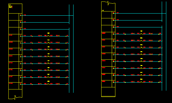
In the Following Example: 8 digital IO channels, a power and a common were placed on each card construction. NB: The IO symbol "continuation blocks" are inserted where the card has been separated.
A "Split" Card.
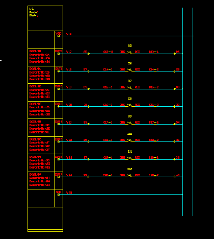
Alternatively you can insert individual IO point into your drawing. This can be done by ticking the box. Now only the IO point named in the list will be inserted into the drawing. When you use , continuation blocks are not inserted above and below the drawing for the IO point.
If you have also ticked the box in step 1c of this procedure to omit the wiring, then the single block for the single IO point is inserted exactly like a device. When it is inserted over a line it will break the line at the terminal(s), for example into an existing ladder diagram.
Stage 4: Position the Card on the sheet and construct
The final stage of construction is to click the finish button drag the bounding box of the card on to the drawing and insert it.
PLC Wizard will then construct the card.
The individual blocks of the PLC card are associated together in a GROUP so they can be treated as a single entity in the drawing. If you need to modify the individual elements of a PLC card that is inserted in a drawing you will need to turn group selection off. Press Ctrl+Shift+A to turn group selection off and press Ctrl+Shift+A to turn group selection on again.
PLC Wizard window will display a question dialog which will ask whether you would like to draw another PLC IO Card. Click "Yes" to continue drawing another PLC I/O Card or "No" to quit.