IO Component Specification
Previous/Next stages
Define the CARD and choose wiring macros for the IO channels
Define the field wiring and marshalling IO components
Stage 2: IO Component Specification
Define the field wiring and marshalling IO components
IO Component Dialog
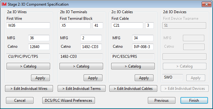
The IO component dialog is divided into 4 areas, one for each component type: , , , . Each area provides the same functionality for a different component type. In the instructions below, the functionality for only area , has been described. The instructions apply equally to the other 3 areas.
Upon entry, the IO component dialog will have been supplied 4 lists of IO components. These lists of components will be used in order to set the attributes of the wire marker, terminal, cable and device symbols that are contained in the chosen wiring macros when the macros are inserted.
The lists will have been created from the combination of the card channel count and the number of wires, terminals, cables and devices found in each of the wiring macros selected for the card channels in the Stage 1: dialog.
For example if our card had 4 input channels only, each with an IO macro containing 1 wire and 1 terminal, then we would have now have lists containing 4 terminals, 4 wires, 0 cables and 0 devices.
An empty list will cause the related area on the dialog to be "greyed out" and disabled.
The IO Wires Area
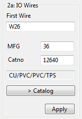
The IO Wire area (and the other 3 areas) can be used to select a "primary" item for the list of IO wires. The primary item can have a tag name and an associated catalog specification.
can be used to select a new catalog specification for the primary item.
The tag name can be entered as desired.
The primary item will not be transferred to the device list until is clicked. When is clicked, all of the devices in the devices list will be loaded with the catalog specification from the primary item and an incrementing series of tag names based upon primary tag name.
To edit the components individually from one of the four lists, click the appropriate button.
Edit Individual IO component dialog
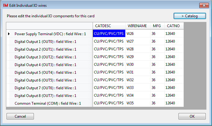
The Edit Individual IO Component dialog allows you to type, cut, paste and "catalog re-select" the IO component data in the list. You can override the default component names and catalog specifications in this list for one or more components.
You may highlight one or more components that you wish to re-select from the catalog and then use the button to select a replacement specification for those highlighted components.
Next Stage
After selection of your IO wiring components, click to save the PLC configuration data to a file.
To begin the Construction stage, you must run PLC Wizard from Elecdes.