Custom Loop Diagram Templates
To create a loop diagram that is more complex than a simple twin conductor loop, it is necessary to use a custom loop template. On such a template all the graphical elements of the diagram must be provided. No loop component templates will be inserted into the diagram. In this way it is possible to construct a loop diagram whose graphical appearance is completely configurable. The only information inserted into a custom loop diagram from the project database is textual data inserted through the template formulae system.
Custom loop diagrams can have other sub-loop diagrams inserted into them to create the final diagram.
Custom loop diagram templates can be found in the <EDS>\IMP_IM\LPCustomTemplates directory for imperial units or the <EDS>\MET_IM\LPCustomTemplates directory for metric units.
Example custom loop template
Tables for Custom Loop Diagrams
Each custom loop template will generally have its own database table of custom loop diagram records.
The column structure of the database table for each custom loop template is based on the number of components to be linked to that custom loop template and this varies between templates. Instrument Manager includes functions to create or update the column structure of tables to match the contents of a custom loop template.
How to Build a Custom Loop Table
-
Select the custom loop template for which you wish to build a table.
You can select multiple custom loop templates in the list view if you wish to make a table with columns to use with multiple templates. These multiple templates should have similar column requirements.
-
Choose "Build Custom Loop Table" from the pop-up menu.
-
Enter a name for your new custom loop table.
If you have selected a single custom loop template then it will be set as the default template for the new custom loop table.
How to Update the Column Structure of a Custom Loop Table
-
Select the custom loop template for which you wish to update the column structure of a table.
You can select multiple custom loop templates in the list view if you wish to update a table with columns linked to multiple templates.
-
Choose "Update Custom Loop Table(s)" from the pop-up menu.
-
Choose one or more tables to be updated with the column structure of the previously selected custom loop template(s).
-
Alternatively select the custom loop table in the tree and choose "Update Custom Loop Table" from the pop-up menu to update a specific table.
You can use the Update procedure to add the columns of a custom loop template that was omitted from the creation of the initial table (possibly because it was not available when you originally built the table).
Assigning Components to Custom Loop Diagram Links
Custom loop diagrams must have each instrument, device, cable and terminal strip in the loop circuit assigned to specific "links" on the loop diagram. (Simple, automatically drawn loop diagrams have only an instrument assigned to them and the remainder of the loop circuit is determined automatically by Instrument Manager.)
Descriptions for links should be defined on every custom loop template to assist you to identify each link when you are assigning components to a custom loop.
The type of the component can optionally be specified for each component link to assist you to assign the correct component type to each link.
A hint should be specified for every component link except the first so that Instrument Manager can automatically assign all of the components from the assignment you make to the first link.
Formulae and Links
Custom Loop templates support standard EDS formula syntax. Fields specified in formulae can be Columns, Relational Columns, or Link Descriptions.
Columns and Relational Columns specified as field names in formulae are resolved from the record of the custom loop diagram. This is different to the other types of diagrams, where formulae are resolved from the record of the instrument.
In every field that is to reference a component for a custom loop diagram, you must identify the link (e.g. L3:) for the component that will supply the data. You will assign a different component to each link. You must also supply any relational link (e.g. L3:P1:) and the column name (e.g. L3:P1:Tagname) for the data that is to be loaded into the diagram.
Any field that does not contain a link relationship will be loaded from the columns of the database record of the custom loop itself (typically values to use in a title block).
The description, component-type filter and hint for each link is stored in a special field that does not set any text or attribute on the final loop diagram. This type of field is only used to specify the description etc. for the link. This type of field starts with "L3=...", as described below.
Links
The custom loop template contains numbered link relationships for each of the components that must be assigned to the diagram, e.g. L1: for the first component link, L2: for the second component link and L3: for the third component link. Link numbers do not need to be contiguous. You may start with L100: followed by L101:, L200: then L250: if that suits your requirements.
The field names for title block attributes do not require a D1: prefix because the fields are resolved directly from the record of the custom loop diagram, unlike those on a simple automatically drawn loop diagram.
Assigning Only the First Terminal or Core / Conductor - Sibling Relationships
It is normal for terminals or cores / conductors to be assigned to links on a custom loop diagram rather than terminal strips or cables. It is by this method that you can specify the first terminal or core / conductor from a long terminal strip or large multi-core or multi-conductor cable that is part of this loop.
It is not necessary to define a new link for every terminal or core / conductor. The second, third and successive terminals or cores / conductors from a terminal strip, device or cable can be referenced using sibling relationships.
To reference the second terminal or core / conductor, enter "+1" after the link number. To reference the third terminal or core / conductor, enter "+2" after the link number, e.g. #L5+2:Tagname#. [In this example L5 should be a terminal or core component type.]
Link Descriptions
Description for Each Link
A description is defined by entering the link number followed by an equals sign "=" followed by the description. For example, #L3=J-Box T-Strip#, means that the link L3 will be identified in the Instrument Manager user interface as "J-Box T-Strip" when assigning components to the loop diagram.
The formula that contains the description does not appear on the final loop diagram, so it can be placed anywhere on the custom loop template. The description formula should be a simple CAD text entity.
Descriptions for links are optional but highly recommended.
Component Type for Each Link
The component type is specified after the description, after a semicolon.
For example, #L3=J-Box T-Strip;Terminal#, specifies that only a terminal can be assigned to "J-Box T-Strip" (link L3) on the loop diagram. This "filtering" of the type of component allowed in a link is optional.
The component type text must be exactly correct as it must match the type in the program. This includes spaces between words, e.g. "TERMINAL STRIP". The default supported types are:
AREA, ENCLOSURE, INSTRUMENT, DEVICE, PLC CARD, TERMINAL STRIP, TERMINAL, TERMINAL GROUP, CABLE, CORE, WIRE, TANK, VALVE, LINE and LOOP DIAGRAM.
Master and sub loop diagrams
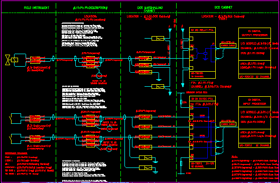
You can create custom loop diagrams that are a composite of two or more drawings. A master template is designed to have sub-loop drawings inserted at specific locations to complete the drawing. Note that the sub-loop drawings are themselves output diagrams created from their own loop templates. For example, in a card-based I/O diagram the master template may contain the border and the I/O card, while the loops for the I/O channels are inserted as sub-loops.
The loop diagram record is assigned to the link using the same method that components are assigned to links. The loop diagram that is to be the sub-loop can be dragged and dropped onto the loop diagram record that is the master loop, or the sub-loop diagram record can be resolved by hints.
The component type for a link for a sub-loop drawing is "Loop Diagram" and should be specified in a descriptive formula for the link. For example, #L11=Loop for channel 1;Loop Diagram#, specifies that only a "Loop Diagram" can be assigned to the link L11 which is described as "Loop for channel 1".
The insertion point for a sub-loop diagram is specified by creating a TEXT entity containing a formula that contains only the link, e.g. #L11#. Note that this cannot be an MTEXT entity. This special formula to define the insertion point for the sub-loop can be placed in model space or a paper space layout and the sub-loop will be inserted into that same drawing space.
Excluding the sub diagrams in database reports
You can choose to exclude the sub loops diagrams in your database reports by right clicking on the sub loop folder and CHECKING the option "Folder contains SUB diagrams". This will exclude the sub diagrams of the selected sub loop folder from database reports.
Controlling setting of the D1 link from the component
When a component is manually assigned to a custom loop link, the D1 (loop diagram) link in the component's record is set to the custom loop. If the assignment is made by a hinted link then it will only set the D1 link in the component's record if the D1 link is currently empty.
When a terminal or core/conductor is assigned to a custom loop link, the D1 link of the terminal or core's parent (device, instrument, cable...) is set to the custom loop.
Having a component linked via D1 to its loop diagram is useful for verifying the presence and name of the loop diagrams for the components, navigation between component and diagram in the category tree, and the D1 link is used by the SLP hint for automatically resolving a sub-loop diagram record.
You can determine whether D1 is always set or never set when a component is assigned to a custom loop link by using one of two codes after the hint (described below) in the descriptive field.
Append D1 to specify that the D1 link from the component will be set to the custom loop.
Append D0 to specify that the D1 link from the component will not be changed.
For example, #L101=Instrument on first channel; Instrument; (...hint...); D0#, specifies that when an instrument is assigned to the L101 link of this custom loop, the D1 column of that instrument is not set to this custom loop.
It is useful to prevent setting D1 when a component appears on both a master loop and a sub-loop. The component should set D1 to the sub-loop (so the link on the sub-loop should have #...;D1#) but it should not be able to set D1 to the master loop (so the link on the master loop should have #...;D0#).
Remember that if you have links for instrument or device terminals on a master loop, then you will also need the ";D0" suffix for the terminals to prevent the instrument or device from being D1-linked to the master loop.
Examples of Formulae:
| #L1:<XTAG># | The configured tagname of the component assigned to L1. |
| #L1=Pressure Inst;Instrument# | The first component link is called "Pressure Inst" and requires an instrument. |
| #L3:Tagname# | The value from the Tagname column of the tag record of the component assigned to L3. |
| #L3:P1:Tagname# | The Tagname of the parent or container of the component assigned to L3. |
| #L4=JBox;Terminal# | The fourth component link is called "JBox" and requires a terminal. |
| #L4:P1:Tagname# | The Tagname of the parent or container of the terminal assigned to L4, which will be a terminal strip given that the L4 component must be a terminal. |
| #L4:<Enclosure># | The value from the <Enclosure> alias of the terminal assigned to L4. |
| #L4:R1:Size# | The value from the Size column of the rating record of the terminal assigned to L4. |
| #L5=Inst Cable;Core# | The fifth component link is called "Inst Cable" and requires a core / conductor. |
| #L5:Tagname# | The value from the Tagname column of the tag record of the core / conductor assigned to L5. |
| #L5+1:Tagname# | The Tagname of the next core / conductor following the core / conductor assigned to L5. |
| #L5:<Cable># | The value from the <Cable> alias of the core / conductor assigned to L5. |
| #Title# | The value from the Title column of the loop diagram record. |
| #Drawn By# | The value from the Drawn By column of the loop diagram record. |
| #PJ:Contract# | The value from the Contract column of the one and only record of the global ProjectData table. |
| #L11=Loop for channel 1;Loop Diagram# | The 11 link is called "Loop for channel 1" and requires a loop diagram. |
| #L11# | The sub-loop diagram that is assigned to L11 will be inserted at the insert point of the text entity containing this formula. |
Hints for Links
Hints in custom loop formulae enable Instrument Manager to derive a component assignment for one link from the component assignment you make manually to another link.
Only one hint can be specified for each link. The hint in the link description tells Instrument Manager what component to assign to the link that contained the hint.
Every time a component is assigned to a link, Instrument Manager will check the hints of all other links to see if they refer to the link that was just assigned. It will then check if it can now derive the component assignment from each of those hints that refer to the new assignment. These automatic assignments may then enable Instrument Manager to derive other component assignments.
Hints for assigning components to links are optional but highly recommended. You should aim for the ideal template design where you assign only the instrument(s) manually then Instrument Manager can derive all of the other component assignments from hints.
Hint Format
The hint for a link follows a semicolon after the component type filter, which follows the description. The hint is enclosed in round brackets. The hint starts with a hint type followed by a semicolon. Following the semicolon is one or two of the other Ln link relationships, separated by a comma, from which to derive the hinted component.
For example, #L11=Field Junction Box - First term; Terminal; (TNE; L7, L1:K1)#.
-
Link: L11.
-
Description: Field Junction Box - First term.
-
Component type filter: Terminal.
-
Hint: (TNE; L7, L1:K1).
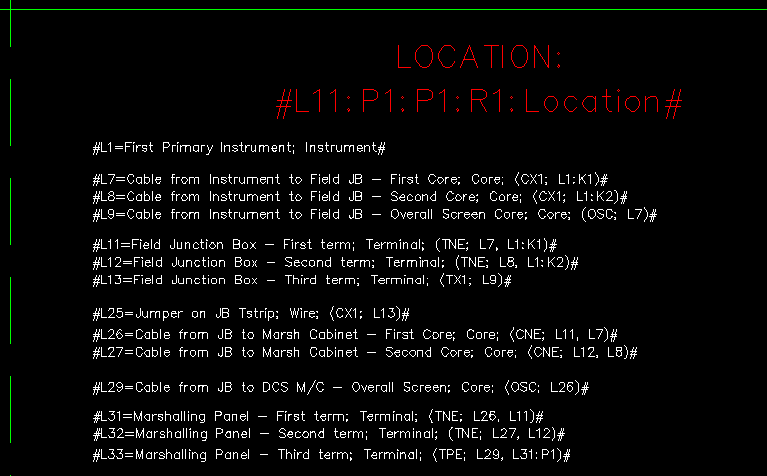
Example of descriptions, types and hints for custom loop formulae
DIR - Direct hint - e.g. #L90=...; (DIR; L1:A10)#
The component referenced by the Ln link relationship in the hint is the component to assign to this link.
If a component is assigned to the link referenced by the hint, then Instrument Manager can directly fetch the required component from the relationship in the hint.
In the example, if an instrument is assigned to link L1, then the desired component is specified by the A10 relationship of that instrument. A10 is an association of an instrument to the terminal group of its ultimately connected PLC channel. That terminal group will be assigned to L90.
CX2 - Conductor connected between two assigned terminals - e.g. #L22...; (CX2; L1:K2, L32)#
Use this hint when you will have assigned two terminals and wish to identify the conductor connected between them.
The desired component is a conductor that will be connected between the two terminals specified by the two Ln link relationships in the hint.
The conductor cannot be a jumper wire between terminals on a terminal strip. If the two terminals are from the same terminal strip and the conductor is a jumper wire, you must use the JX2 hint.
In the example, if an instrument is assigned to L1 and a terminal from a junction box terminal strip is assigned to L32, then the desired component is a conductor connected between the second terminal (K2) of the instrument and the junction box terminal assigned to L32. That conductor will be assigned to L22.
Given that most hints will be resolved from an assignment at one end of the loop, you are unlikely to have assigned the terminal at the far end of the conductor, so you are more likely to require CX1 and CNE than CX2.
CX1 - Conductor connected to one assigned terminal - e.g. #L22...; (CX1; L1:K2)#
Use this hint when you will have assigned a terminal and wish to identify the single conductor connected to that terminal.
The desired component is a conductor that will be connected to the terminal specified by the Ln link relationship in the hint. This hint is useful only if the terminal is connected to only this one conductor.
This hint will not find a jumper wire between terminals on a terminal strip. Therefore, if the terminal has both the conductor and it has a jumper wire, then the CX1 hint can still be used because the jumper wire will not match. If you are instead trying to identify the jumper wire, use JX1.
In the example, if an instrument is assigned to L1, then the desired component is the single conductor connected to the second terminal (K2) of the instrument. That conductor will be assigned to L22.
Given that the loop usually starts at an instrument and the instrument terminals each have only a single connection, CX1 hints are most often used to identify the cores / conductors of the instrument cable.
CPE - Conductor from an assigned cable that is connected to an assigned terminal - e.g. #L43...; (CPE; L33, L41:P1)#
Use this hint when you have assigned a terminal and wish to identify the conductor connected to that terminal, from the same cable as another conductor that is already assigned.
The desired component is a conductor that will be connected to the terminal specified by the first Ln link relationship in the hint and the conductor will be from the cable specified in the second Ln link relationship in the hint.
In the example, if a terminal from the junction box is assigned to L33 and the first core from a multi-core or multi-conductor cable is assigned to L41, then the desired component is a conductor from the specified multi-core or multi-conductor cable (L41:P1) that is connected to the junction box terminal. That conductor will be assigned to L43.
CPE hints can be used to identify cable screens or spare cores / conductors if the terminal to which they connect will already be assigned. PSC, TSC and OSC are more logical choices for identifying cable screens or shields.
CNE - Conductor connected to one assigned terminal, which is not equal to another assigned conductor - e.g. #L42...; (CNE; L32, L22)#
Use this hint when you will have assigned a terminal and a conductor on one side of that terminal and wish to identify the conductor connected to the other side of that terminal.
The desired component is a conductor that will be connected to the terminal specified by the first Ln link relationship in the hint and the desired component will not be the same as the conductor specified by the second Ln link relationship in the hint.
This hint will not find a jumper wire between terminals on a terminal strip. If the terminal also has a jumper wire then the CNE hint can still be used because the jumper wire will not match. If you are instead trying to identify the jumper wire, use JNE.
In the example, if a junction box terminal is assigned to L32 and a core / conductor from the instrument cable is assigned to L22, then the desired component is the conductor connected to the DCS side of the junction box. That conductor will be assigned to L22.
JX2 - Jumper wire connected between two assigned terminals - e.g. #L101...; (JX2; L27, L30)#
Use this hint when you will have assigned two terminals on a terminal strip and wish to identify the jumper wire connected between them.
The desired component is a wire that will be connected between the two terminals specified by the two Ln link relationships in the hint. Both of the terminals specified in the hint must be from the same terminal strip. The desired component must be a wire, not a cable core/conductor.
If you are instead trying to find a conductor between two different components, use the CX2 hint.
In the example, if two junction box terminals are assigned to L27 and L30, then the desired component is a wire connected between those two terminals. That wire will be assigned to L101.
JX1 - Jumper wire connected to one assigned terminal - e.g. #L101 ; (JX1; L15)#
Use this hint when you will have assigned a terminal and wish to identify the jumper wire connected to that terminal.
The desired component is a wire that will be connected to the terminal specified by the Ln link relationship in the hint. The terminal at the other end of the wire must come from the same terminal strip. This hint is useful only if the terminal is connected to only this one jumper wire.
This hint will not find a conductor that connects to a different component or terminal strip. Therefore, if the terminal has both the link and it has other conductors to other components, then the JX1 hint can still be used because the other conductors will not match.
In the example, if a junction box terminal is assigned to L15, then the desired component is the single wire connected to that terminal. That wire will be assigned to L101.
JX1 hints are most often used to identify the start of a looped wire linking terminals on a strip.
JNE - Jumper wire connected to one assigned terminal, which is not equal to another assigned jumper wire - e.g. #L102 ; (JNE; L18; L101)#
Use this hint when you will have assigned a terminal and a jumper wire entering that terminal and wish to identify the jumper wire leaving that terminal (continuation of a looping jumper wire).
The desired component is a wire that will be connected to the terminal specified by the first Ln link relationship in the hint and the desired component will not be the same as the wire specified by the second Ln link relationship in the hint. The terminal at the other end of the wire must come from the same terminal strip.
This hint will not find a conductor that connects to a different component or terminal strip. Therefore, if the terminal has both the links and it has other conductors to other components, then the JNE hint can still be used because the other conductors will not match.
In the example, if a junction box terminal is assigned to L18 and a jumper wire connecting to that terminal is assigned to L101, then the desired component is the other wire connected to that terminal that is not the same as L101. That wire will be assigned to L102.
JNE hints are most often used to identify the next loop of a looped jumper wire linking terminals on a strip.
TX2 - Terminal connected between two assigned conductors - e.g. #L32...; (TX2; L22, L42)#
Use this hint when you will have assigned two connected conductors and wish to identify the junction box or marshalling terminal at the point where they connect together.
The desired component is a terminal that will be the connection point for two conductors specified by the two Ln link relationships in the hint.
In the example, if a core / conductor of an instrument cable is assigned to L22 and a core / conductor of the multi-core or multi-conductor cable is assigned to L42, then the desired component is the terminal where the two cores / conductors are connected. That terminal will be assigned to L32.
Given that most hints will be resolved from an assignment at one end of the loop, you are unlikely to have assigned the conductor at the far side of the terminal, so you are more likely to require TPE and TNE than TX2.
TX1 - Terminal connected to one assigned conductor - e.g. #L33...; (TX1; L23)#
Use this hint when you will have assigned a conductor and wish to identify the only terminal connected to that conductor.
The desired component is the only terminal that will be connected to the conductor specified by the Ln link relationship in the hint. This hint is useful only if the conductor is connected at only one end, most likely the conductor is a shield or screen.
In the example, if the screen from the instrument cable is assigned to L23, then the desired component is the only terminal that is connected to the screen. That terminal will be assigned to L33.
TX1 hints are most often used to identify the terminals connected to the screens or shields of cables. The TPE hint is more reliable than the TX1 hint.
TPE - Terminal from an assigned terminal strip that is connected to an assigned conductor - e.g. #L33...; (TPE; L23, L31:P1)#
Use this hint when you have assigned a conductor and wish to identify the terminal connected to that conductor, from the same terminal strip as another terminal that is already assigned.
The desired component is a terminal that will be connected to the conductor specified by the first Ln link relationship in the hint and the terminal will be from the terminal-strip specified by the second Ln link relationship in the hint.
In the example, if the screen from the instrument cable is assigned to L23 and the first terminal from a junction box terminal strip is assigned to L31, then the desired component is a terminal from the specified terminal strip (L31:P1) that is connected to the instrument cable screen. That terminal will be assigned to L33.
TPE hints are useful to identify the terminals connected to the screens or shields of cables and are more reliable than TX1 hints.
TNE - Terminal connected to one assigned conductor, which is not equal to another assigned terminal - e.g. #L32...; (TNE; L22, L1:K2)#
Use this hint when you will have assigned a conductor and a terminal at one end of that conductor and wish to identify the terminal at the other end of that conductor.
The desired component is a terminal that will be connected to the conductor specified by the first Ln link relationship in the hint and the desired component will not be the same as the terminal specified by the second Ln link relationship in the hint.
In the example, if a core / conductor of an instrument cable is assigned to L22 and an instrument is assigned to L1, then the desired component is the junction box terminal at the other end of the instrument cable - i.e. the desired terminal is not the second terminal (K2) of the instrument. That terminal will be assigned to L32.
OSC - Overall screen from an assigned cable - e.g. #L49...; (OSC; L41)#
Use this hint when you will have assigned a core / conductor of a cable and wish to identify the screen or shield of that cable.
The desired component is a conductor that represents the overall screen or shield for a cable that includes the conductor specified by the Ln link relationship in the hint.
In the example, if a core / conductor from a cable to a marshalling cubicle is assigned to L41, then the desired component is the overall screen or shield from the cable. That screen or shield will be assigned to L49.
PSC - Pair screen for an assigned core / conductor - e.g. #L43...; (PSC; L41)#
Use this hint when you have assigned a core / conductor from a screened-pair cable and wish to identify the screen conductor.
The desired component is a conductor that represents the screen for a particular pair that includes the conductor specified by the Ln link relationship in the hint.
In the example, if a core / conductor from a paired cable to a marshalling cubicle is assigned to L41, then the desired component is the screen for the pair that includes the core / conductor assigned to L41. That pair-screen will be assigned to L43.
TSC - Triad screen for an assigned core / conductor - e.g. #L44...; (TSC; L41)#
Use this hint when you have assigned a core / conductor from a screened-triad cable and wish to identify the screen conductor.
The desired component is a conductor that represents the screen for a particular triad that includes the conductor specified by the Ln link relationship in the hint.
In the example, if a core / conductor from a triad cable to a marshalling cubicle is assigned to L41, then the desired component is the screen for the triad that includes the core / conductor assigned to L41. That triad-screen will be assigned to L44.
SLP - Sub-loop for a PLC I/O channel - e.g. #L1011...; (SLP; L1001)#
Use this hint when you have assigned a PLC I/O channel (a terminal group of a PLC card) to a card-based I/O diagram and wish to identify the sub-loop diagram that should be inserted for that channel.
The desired component is another loop diagram (called a sub-loop diagram) that would typically appear incomplete and would have no border because it is designed to be inserted into the master diagram.
In the example, if a PLC I/O channel (a terminal group) is assigned to L1001, then the desired component is the loop diagram of the instrument that is associated with that I/O channel.
This hint requires, in the database, an instrument with a loop (linked by D1) that has been associated with the I/O channel (via A10). This hint is exactly equivalent to the hint (DIR; Lxx:~A10:D1) - e.g. from the example above, the equivalent hint using DIR is #L1011...; (DIR; L1001:~A10:D1)#. The SLP hint provides a shortened version of that hint.
Using Relational Aliases in Hints
Hints can make use of relational aliases for the relationships in the hint. The primary advantage is that a relational alias can resolve to one of a number of relational columns to match the component type specified in the alias. Other advantages are that relational aliases can be more concise, easier to understand on the drawing, and easier to remember. A relational alias actually specifies a specific column of data to fetch but this is ignored when resolving hints, so it does not matter which specific column is fetched as long as the correct record is resolved.
e.g. #L4=...; Area; (DIR; L32:<Area>)#
In the example, if a terminal from a junction box is assigned to L32 and you wish to find that terminal's area to assign to L4, then the desired component is the area resolved by the alias <Area> from the terminal's record using the relationship L32:<Area>. For a junction box terminal this link and alias would likely resolve to the relationship L32:P1:P1:P1:Tagname, from which the hint uses only the part L32:P1:P1:P1, but L32:<Area> is easier to use and visualise.
Required Component and Recommended Hint
| A component directly related to another component, e.g. a terminal of an instrument, or the I/O channel for the instrument (the instrument can be linked to its PLC terminal group), or the junction box (enclosure) containing a JB terminal. | DIR |
| A conductor of an instrument cable, the first connections on the loop. | CX1 |
| A conductor of the multi-core / conductor cable on the other side of the junction box from the instrument cable. | CNE |
| The screen for a one-pair or one-triad instrument cable. | PSC, TSC or OSC |
| The screen for a pair or triad in a multi-core or multi-conductor cable. | PSC or TSC |
| The overall screen or shield for a multi-core or multi-conductor cable. | OSC |
| Spare from a multi-core / conductor cable that is connected out to the junction box but not to an instrument cable. | CPE |
| A junction box terminal connected to a pair or triad of the instrument cable. | TNE |
| A junction box terminal on the other end of a jumper wire. | TNE |
| A junction box terminal connected to a screen or shield. | TPE |
| A jumper wire between two known terminals on a terminal strip. | JX2 |
| The first loop of a jumper wire connected to a junction box terminal. | JX1 |
| The next loop of a jumper wire connected to a junction box terminal. | JNE |
Optional links
If a link has no component assigned to it then Instrument Manager will warn you and the status of the Custom Loop will report "Loop items missing". In some cases you might expect a link to stay unassigned for some diagrams, e.g. a spare channel on a PLC I/O card diagram. You can flag such links as optional and Instrument manager will ignore them if they are unresolved. To flag a link as optional add the OPTIONAL keyword to the link formula after the D0/D1 flag, separated by a semicolon.
For example:
#L10=2nd Inst;Instrument;;;OPTIONAL#
#L11=2nd Inst 1st Term;Terminal;(DIR; L10:K1);D0;OPTIONAL#
Those two link-formulae specify that the links L10 and L11 are optional, so the diagram can be reported as complete even if those links remain empty.
Manipulating Graphics with Formula Functions
In addition to standard formula functions for manipulating text, Custom loop templates support formula functions that can be used to manipulate the graphics on a generated custom loop diagram. These functions can be used to create a custom loop template with dynamic graphics as well as dynamic text, thus allowing a single template to be used in place of several individual templates that each have minor graphical differences.
As with with standard functions, the parameters supplied to these functions can be any formula expression (fixed text or numbers, source data fields, or other functions).
These DWG manipulation formula functions all return empty strings, so they can be used transparently anywhere a formula can be used (such as TEXT entities and block attributes) without leaving a trace. Combine them with logical functions like IF to conditionally modify graphics based on columns in the custom loop record itself, or any of the linked components.
Elecdes Compatibility
It is sensible for users who have Elecdes to make their custom loop templates compatible with Elecdes. The diagrams will then, in their own right, be intelligent and can be used in downstream automation tasks provided with Elecdes.
This is not compulsory. Your custom loops can be created with any background graphic creation and simple text entities can hold the cable numbers, instrument tags etc.
Learn from the Samples
We have supplied examples of custom loop templates and included in our supplied database templates a pre built table that will allow you to use this custom loop as a learning tool or example to copy.