Output Diagram Templates
Templates are used as the basis of the output diagrams. They contain the formatting and layout elements of the documents and have textual formulae placed on them to mark where information from the project database will be substituted.
Each template that can be used in an output diagram requires a record in the project database. For each of the five types of templates there is a table in the database where the records for the templates exist. Templates can be added and removed from the tables in a similar fashion to components in the project database.
The generation of output diagrams from templates is very similar to the system used by the EDS Protogen module. The same standard EDS formula syntax is used, but in Instrument Manager, the fields used in formulae can also be relational columns or aliases, which make it possible to lookup relational data.
The formulae on a template will be displayed in the list view of Instrument Manager when a template is selected in the tree.
Templates can be viewed and edited using an editor native to their file format. This will be your CAD package for DWG files and Microsoft Excel for XLS, XLSX, XLSM or XLSB files. To view or edit a template, right click on the desired template and select "Edit/View" from the pop up menu. Instrument Manager will run the appropriate application and open the template file.
Datasheet Templates
Instrument datasheet templates are Microsoft Excel XLS, XLSX, XLSM or XLSB format spreadsheet files. The formula fields on the templates generally map the cells in the datasheet to columns in the instrument tag and ratings records. Formulae in the title block map to the columns in the record for the datasheet itself.
In Datasheet templates, relational columns fields on the template are resolved from the tag record of the instrument. As an example, if an #R1:CATDESC# formula were used on any datasheet template then it would be the CATDESC column of the RATINGS record of the first INSTRUMENT on that datasheet that will load into the formula. A #D2:Title# formula would fetch the TITLE column of the datasheet record.
TIP: To make a company logo easy to change on the datasheet without using a new set of templates, in Excel use "Link to file" instead of "Insert" on the file choice dialog when placing the logo. You can then change the content of the image file and the new image will appear on the datasheets, without having to change your templates.
Datasheet templates can be found in the <EDS>\IMP_IM\DSTemplates directory for imperial units or the <EDS>\MET_IM\DSTemplates directory for metric units.
The Generic_Instruments datasheet template is not specific to any particular type of instrument. This template can also be used as a base for creating new datasheet templates for new instrument types.
Datasheet templates are the mapping files for importing data from datasheets.
Loop Diagram Templates
These are AutoCAD DWG files. Diagrams of this type are used as a basis for loop output diagrams. There are two types of loop diagram template that can be used in Instrument Manager.
Loop templates for simple automatically drawn loops
Simple loops have a standard twin conductor connection from the instrument to the DCS. These loop circuits can be derived and drawn automatically by Instrument Manager. A simple loop template will typically contain graphical elements for a border, title block and other items not related to the electrical components. The title block should have formula fields linking text or attribute entities on the diagram to columns from the loop diagram record in the project database. The electrical elements of the diagram (the loop itself) will be inserted by Instrument Manager when the diagram is generated - these are the loop component templates described below.
In simple automatically drawn loop diagrams, relational columns fields on the template are resolved from the tag record of the instrument. As an example, if an #R1:CATDESC# formula were used on an attribute on a template then it would be the CATDESC column of the RATINGS record of the first INSTRUMENT that will load into the attribute. A #D1:Title# formula would fetch the TITLE column of the loop diagram record.
Simple loop diagram templates can be found in the <EDS>\IMP_IM\LPTemplates directory for imperial units or the <EDS>\MET_IM\LPTemplates directory for metric units.
Anchor points for templates for simple automatically drawn loops
By default, the placement of the components on a Loop diagram is determined by the Loop Generation Settings. It is often the case that a designer needs to specifically position the component stages of a loop diagram (e.g. the instrument, the junction box, the marshalling panel and the PLC… etc.) at a predefined and exact point on the final loop diagram.
A designer creating an “auto loop template” can create one or more “Anchor Point” text entities on the template.
To insert an anchor point on the template, simply insert a text entity at the desired position and set the text to the following row and column formula. The format for the row and column formula is #_R<row>C<column>#.
For example, if the formula says #_R1C2#, the second stage in the first circuit will be inserted at the insertion point of the anchor point text entity.
Template example:
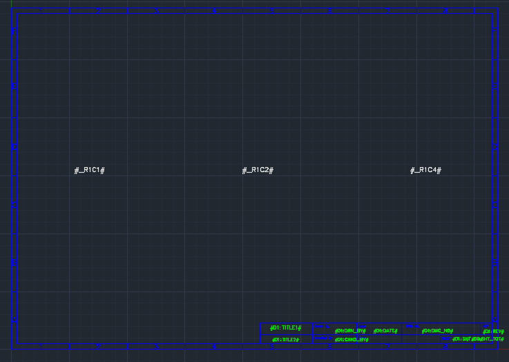
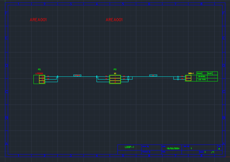
Diagram Generated:
Rules:
You must have the anchor point for the first stage in the first circuit(#_R1C1#) present in the template, if you want the Loop drawer to use the anchor points to position the stages from all the circuits in the Loop Diagram.
The number of stages in the loop diagram does not need to match the number of anchor points in the template. The Loop drawer can use the existing anchor points and extrapolate the positions for stages that do not have an anchor point.
You can also use special power anchor points for components in a power connection. The formula for the power anchor points are #_P<row>C<column>#, where <row> is the index of the main circuit, for which the power connections are being drawn, and <row> is the index of the stage in the power circuit.
If there are no power anchor points present in the template, standard anchor points will be used for the stages of a power connection circuit that needs to be drawn for an instrument.
Custom Loop Templates
Custom loop templates are used to generate loop diagrams which have connections that are complicated and that "branch out" from the standard twin conductor connection between an instrument and the DCS.
A custom loop template should contain a template for the graphical elements of the entire loop circuit. This allows a completely customisable loop diagram to be created in any free form layout.
Custom loop templates contain relationships in order to connect to and load data from several components in the database. These relationships are NOT resolved in the same way as with simple automatically drawn loops. Please read the following linked section if you wish to create and use "Custom loops".
Loop Component Templates
These are AutoCAD DWG files. Simple loop diagrams are constructed automatically by Instrument Manager by inserting many small "loop component" template drawings, one for each component, onto the otherwise empty loop diagram template, thus building a connected loop circuit. Each component is represented by a loop component template appropriate to that component.
Custom loops do not use the loop component templates.
In loop component templates, relational column fields on the component template are resolved from the tag record of the component that the template represents. It could be a cable, wire, instrument or other. As an example, if an #"R1:CATDESC# formula were used on an attribute on a component template for a device then it would be the CATDESC column of the RATINGS record of the DEVICE that is being inserted that will be loaded into the attribute.
Loop component templates can be found in the <EDS>\IMP_IM\LPComponentTemplates directory for imperial units or the <EDS>\MET_IM\LPComponentTemplates directory for metric units.
Each component can be configured to use a specific loop component template. If a specific template is not configured it will use the default loop component template for its component type.
Loop Component Template Offsets and Width
Specific loop component templates may require positional information to ensure that they are placed correctly in the output diagram to align with other loop component templates. This information is supplied in two columns of the record for the loop component template. The two columns are provided with both a metric and imperial prefix, Met or Imp respectively, so that the differently scaled values do not overwrite each other.
The two columns are described below:
| Column | Description |
|---|---|
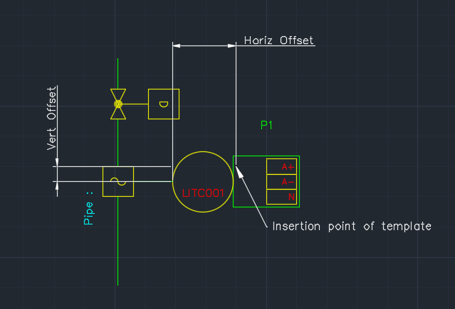
| Horiz Offset | Specifies the horizontal distance from the point in the loop diagram at which the template will be inserted to the origin point (0,0,0) of the template. |
| Vert Offset | Specifies the vertical distance from the point in the loop diagram at which the template will be inserted to the origin point (0,0,0) of the template. |
Notes:
- Existing databases may also contain additional columns like Width, Term Horiz Offset and Term Vert Offset. These columns are not used anymore.
If these columns are blank in the record for the loop component template, the default settings will be used from Loop Generation Settings.
The Loop component templates for terminals and conductors do not use these columns. The positional information is directly calculated from the loop component template for teminals and conductors.
-
The insertion point of the loop component templates for terminals must be at the top left of the terminal.
-
The insertion point of the loop component templates for conductors must be at the beginning of the conductor line.
Loop Component Template override for conductors
When a core/wire is being drawn in a Loop diagram, a pair of loop component templates are inserted based on the type of the connection and the number of connections on the terminal.
Based on the number of connections on a terminal, a core/wire will include one of the following symbols:
| Loop Generation Setting | Template Name Suffix | Description |
|---|---|---|
| Main Conductor Input Symbol | CondLeft | Symbol for the main conductor connected into the left of a component. |
| Main Conductor Output Symbol | CondRight | Symbol for the main conductor connected out from the right of a component. |
| Secondary Conductor Input Symbol | CondDownLeft | Symbol for the secondary conductor branching into the left of a component. |
| Secondary Conductor Output Symbol | CondDownRight | Symbol for the secondary conductor branching out from the right of a component. |
Based on the type of the connection, the core/wire will also include one of the following symbols:
| Loop Generation Setting | Template Name Suffix | Description |
|---|---|---|
| Core Main Conductor Input Symbol | CoreLeft | Symbol for a core connected into the left of a component. |
| Core Main Conductor Output Symbol | CoreRight | Symbol for a core connected out from the right of a component. |
| Core Open Circuit Input Symbol | CoreOpenCctLeft | Symbol for a core connected into the left of a component, disconnected on the other end. |
| Core Open Circuit Output Symbol | CoreOpenCctRight | Symbol for a core connected out from the right of a component, disconnected on the other end. |
| Core External Input Symbol | CoreExternalLeft | Symbol for a core connected into the left of a component, connected externally on the other end. |
| Core External Output Symbol | CoreExternalRight | Symbol for a core connected out from the right of a component, connected externally on the other end. |
| Wire Main Conductor Input Symbol | WireLeft | Symbol for a wire connected into the left of a component. |
| Wire Main Conductor Output Symbol | WireRight | Symbol for a wire connected out from the right of a component. |
| Wire Open Circuit Input Symbol | WireOpenCctLeft | Symbol for a wire connected into the left of a component, disconnected on the other end. |
| Wire Open Circuit Output Symbol | WireOpenCctRight | Symbol for a wire connected out from the right of a component, disconnected on the other end. |
| Wire External Input Symbol | WireExternalLeft | Symbol for a wire connected into the left of a component, connected externally on the other end. |
| Wire External Output Symbol | WireExternalRight | Symbol for a wire connected out from the right of a component, connected externally on the other end. |
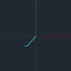
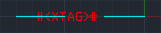
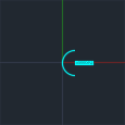
For example, if the template for the Main Conductor Input Symbol (CondLeft) is:
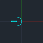
and the template for the Core Main Conductor Input Symbol (CoreLeft) is:
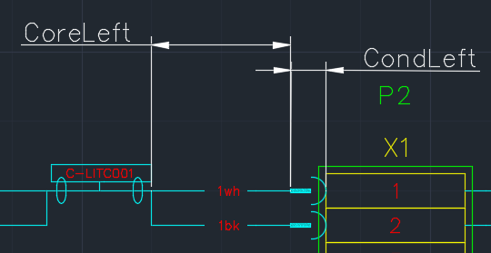
The complete core will be drawn as:
For any pair, triad or overall screens/shields, only one of the following symbols is inserted. The conductor line joining the terminal and the screen will be drawn automatically by the Loop Drawer.
| Loop Generation Setting | Template Name Suffix | Description |
|---|---|---|
| Screen Symbol | Screen | Default symbol for a screen or shield for a pair. |
| Triad Screen Symbol | TriadScreen | Default symbol for a screen or shield for a triad. |
| Downward Screen Symbol | ScreenDown | Default symbol for a screen or shield for a pair, facing downwards. |
| Downward Triad Screen Symbol | TriadScreenDown | Default symbol for a screen or shield for a triad, facing downwards. |
| Overall Screen Symbol | OverallScreen | Default symbol for an overall screen or shield. |
| Overall Screen Open Circuit Symbol | OverallScreenOpenCct | Default symbol for an overall screen or shield, disconnected on the other end. |
| Screen Open Circuit Symbol | ScreenOpenCct | Default symbol for a screen or shield for a pair, disconnected on the other end. |
| Triad Screen Open Circuit Symbol | TriadScreenOpenCct | Default symbol for a screen or shield for a triad, disconnected on the other end. |
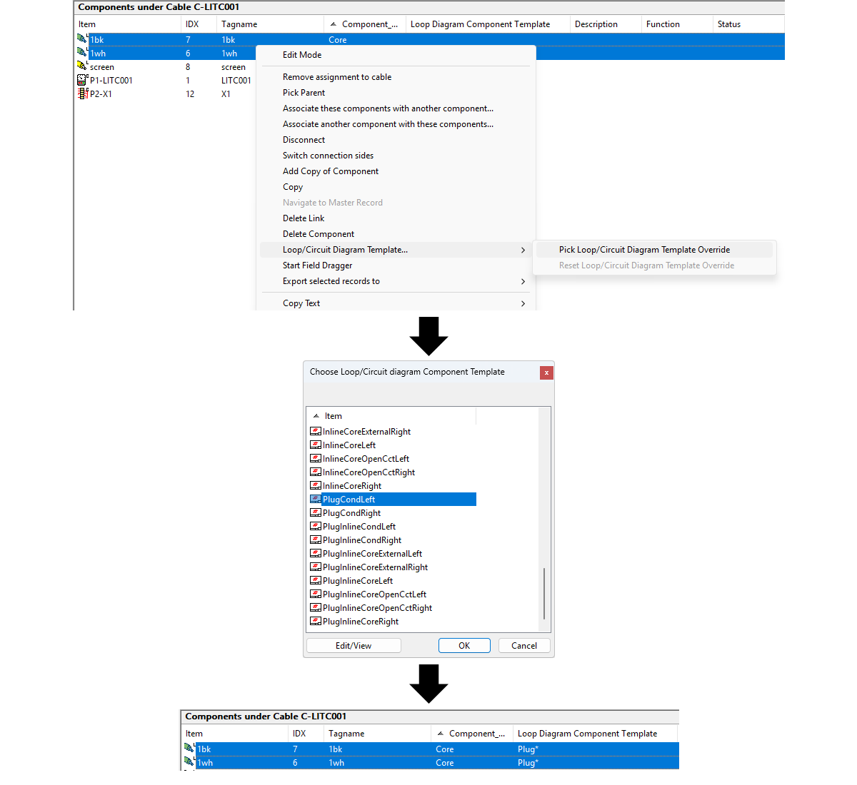
To override the loop component template for a conductor, you will need to set the template name to a family of templates. The family of templates is determined by the prefix of the template names. For example, if you want to override just the CondLeft and CondRight parts of a conductor with a plug symbol, you will need to create two templates with the same prefix. If you decided to name the family, "Plug", the names of the templates would need to be "PlugCondLeft" and "PlugCondRight". The value of the "Loop Diagram Component Template" field for the conductor's record will need to be set to "Plug*". You can manually enter the family name by editing the record OR you can choose any one of the templates from the desired family, using the context menu option "Pick Loop Template Override".
When drawing the conductor on the Loop diagram, the program will build the complete template name, based on the type of the connection, from the family name specified and insert the appropriate template.
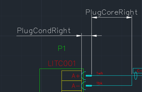
For example, the "Loop Diagram Component Template" for a core's record is set to "Plug*", the core is connected on both ends and the core is the main conductor connected into the terminal. When drawing the core on the output side of the terminal, the Loop drawer will insert the templates named, "PlugCondRight" and "PlugCoreRight".
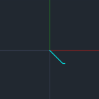
PlugCondRight:
PlugCoreRight:
Drawing:
Notes:
If a template is not found in the family of templates, the default template for that symbol will be inserted. The default template for the symbols can be modified from the Loop Generation Settings.
Loop Stage Templates
Simple loop diagrams contain a number of stages, each representing the components in the circuit. By default, each stage is drawn by inserting a series of Loop Component Templates for all the parts of a stage (enclosure, component, terminal group and terminals). The symbols, orientation and dimensions, for these Loop Component Templates is determined using the global Loop Generation Settings. Typically, to draw most of the components in the circuit, you would only need these Loop Component Templates.
For more complex components, you can create a special template, pre-loaded with all of the parts of a stage. We call this a Loop Stage Template. Loop Stage Templates are AutoCAD DWG files.
A Loop Stage Template, ideally, in a single drawing file, contains all of the parts of a stage (enclosure, component, terminal groups and terminals). A Loop Stage Template offers you flexibility to position and modify the appearance of the multiple parts in a stage.
You can also insert any of the Elecdes terminal symbols (for example, VTTERM symbols) to a Loop Stage Template to represent the terminals of the component and the Loop drawer will automatically locate these and draw any connections to the other stages of the circuit.
To configure a component to use a Loop Stage Template, right click on the component in the Project Tree, select "Pick Loop Stage Template and pick the desired template.
The template can be specified on any component of a stage, ideally on the outermost container component that will appear in only one loop. Do not chose a component that is shared in 2 loops. For Example:
For a small junction box, containing a single terminal strip, in a single instrument loop, the Loop Stage Template could be specified on the enclosure or the terminal strip.
For a component inside a panel containing different types of components on different loops, the Loop Stage Template should be specified on the component, and not the enclosure.
For a single channel on a PLC card where the card contains both input and output channels, and the appearance of an input channel differs from an output channel, the Loop Stage Template should be specified on the terminal group.
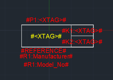
Any formulae in the Loop Stage Template are resolved in the context of the component which had the template specified. For example, if a Loop Stage Template was specified on a device, the terminal symbol should use "#K1:Tagname#" to get the tagname of the first terminal.
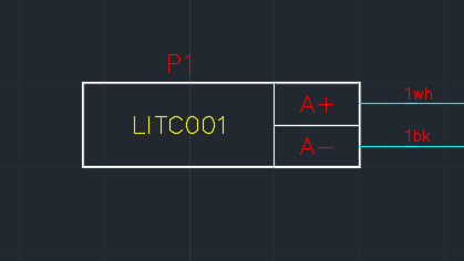
The following example shows a Loop Stage Template for an instrument with two terminals.
Template:
Drawing:
Loop Stage Templates can be found in the <EDS>\IMP_IM\LPStageTemplates directory for imperial units or the <EDS>\MET_IM\LPStageTemplates directory for metric units.
Notes:
If multiple components of a single stage have a template specified, the template chosen will be the template specified in the component which is the outermost container.
When a stage is configured to use a Loop Stage Template, none of the Loop Component Templates for that stage are inserted, because a Loop Stage Template should be complete for that stage.
Hook-up Diagram Templates
These are AutoCAD DWG files. They typically will contain graphical elements describing the shape, position and connection details for instrument mounting hardware. It will also have a border and title block that will appear on a hook-up output diagram. The formula fields on the templates generally map the text or attributes on the hook-up diagram to columns in the instrument tag and ratings records. Formula fields in the title block map to the columns in the record for the hook-up diagram itself.
In hook-up diagrams, relational column fields on the template are resolved from the tag record of the instrument. As an example, if an #R1:CATDESC# formula were used on an attribute or text field on a template then it would be the CATDESC column of the RATINGS record of the INSTRUMENT that will load into the attribute/text. A #D3:Title# formula would fetch the TITLE column of the hook-up diagram record.
Hook-up diagram templates can be found in the <EDS>\IMP_IM\HUTemplates directory for imperial units or the <EDS>\MET_IM\HUTemplates directory for metric units.
Materials from hook-up drawings
The extra materials that are listed in the hook-up drawings (screws, brackets, glands etc), which are used to mount and connect instruments and devices, can be included in the EDS materials reports.
Use an "extra part table" block for each type of item (block name: oeTable.dwg) to create a table of these materials on the hook-up drawing. The contents of extra part blocks is automatically included in the EDS materials reports.
You can insert the extra part table block from the Elecdes "Reference and Indicators" symbol menu. Graphically the extra part table block looks like a single row from a table.
For more information about the materials reports, see How to Add non-Electrical Parts to the Bill of Materials (Ebase).
Terminal Strip and Wiring Diagram Templates
These are AutoCAD DWG files. Templates of this type are used as a basis for terminal strip diagrams for terminal strips or wiring diagrams for devices. They typically will contain graphical elements for a border and title block. The title block should have formula fields that map to the columns in the record for the terminal strip diagram or wiring diagram itself.
In terminal strip and wiring diagrams, relational column fields on the template are resolved from the tag record of the terminal strip or device. As an example, if a #TAGNAME# formula were used on an attribute on a template then it would be the TAGNAME column of the appropriate terminal strip or device that will load into the attribute. A #D4:Title# formula would fetch the TITLE column of the terminal strip or wiring diagram record.
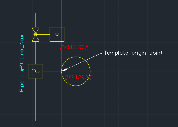
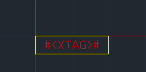
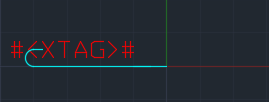
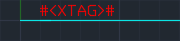
You can also insert a placeholder on the template to indicate that the diagram should be created at that specific position. The placeholder is a Wiring Diagram anchor block, wd_anchor. See How to Use Placeholders to Pre-arrange a Wiring Diagram. Set the TAGNAME and PNLNO attributes of the placeholder block to formulae for the name and panel/enclosure of the terminal strip or device, e.g. TAGNAME = "#<XTAG>#" and PNLNO = "#P1:<XTAG>#".
If you insert multiple placeholders on the template then you should use "Numbered Fields" (as described below) in the TAGNAME and PNLNO attributes so that each placeholder refers to a different component. In the second placeholder block, for the second terminal strip or device on the same template, use the suffix "_2" as follows: TAGNAME = "#<XTAG>_2#" and PNLNO = "#P1:<XTAG>_2#".
Terminal strip and wiring diagram templates can be found in the <EDS>\IMP_IM\TSTemplates directory for imperial units or the <EDS>\MET_IM\TSTemplates directory for metric units./p>
Multiple Components on One Diagram
Multiple components can be linked to a single diagram. For example, a tabular datasheet, or three loops shown on one loop diagram.
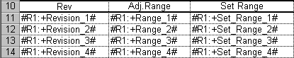
Numbered Fields - #Tagname_3#
The formula fields on a diagram that contains multiple components will be "Numbered fields". Each field will end in an underscore, followed by a component number, e.g. #R1:CATDESC_1# for the first instrument, #R1:CATDESC_2# for the second instrument.
Note that numbered fields are not required for loop diagram templates. The electrical components shown on simple, automatically drawn loop diagrams use loop component templates, which are specific to each component.
Note that numbered fields are not required for custom loop diagram templates. Custom loop diagrams use a different system where the relational column fields are resolved from the record of the custom loop diagram.
Datasheet tabs
On datasheets, multiple components can be shown using numbered fields on one sheet, or as clones of the tabs or sheets.
For example, if you link five instruments to a single datasheet that does not use numbered fields (i.e. it appears to be a template for a single instrument), then the individual sheets within the datasheet template will be cloned for each of the five instruments.
The two methods of showing multiple components can work together. For example, if your template has a single sheet that can show 25 instruments and you link 40 to the diagram, then the final datasheet will contain two sheets, the first containing 25 instruments and the second containing the remaining 15.
If a template is designed to have sheets cloned to show multiple instruments but also contains sheets that should appear only once, you can define a pattern to identify the names of any sheets that should not be cloned in the datasheet preferences.
Component Limits
The record in the project database for each template can optionally specify the maximum number of components that can be shown on a diagram generated from that template. Right click on the desired template and select "Set Component Limit" from the pop-up menu to specify this value. Alternatively, the "Component Limit" column can be edited in the row and column edit mode of the Instrument Manager window. A component limit of "0" indicates that there is no limit specified for that template.
Component Order
The order that multiple components appear on a single diagram can be set by manually assigning a number that represents the position for each component assigned to the diagram. Enter increasing numbers into the appropriate *_Order column of each component tag record.
-
Use DS_Order to arrange components on datasheets.
-
Use HU_Order to arrange components on hook-up diagrams.
-
Use LP_Order to arrange instruments on simple, automatically drawn loop diagrams.
-
Ordering is not necessary for terminal strip and wiring diagrams because the individual components are arranged using the EDS Wiring Diagram Generator.
-
Ordering by a column is not necessary for custom loop diagrams because each component is assigned to a specific link on the custom loop diagram, as described below.
Manipulating Graphics with Formula Functions
In addition to standard formula functions for manipulating text, DWG-based templates support formula functions that can be used to manipulate the graphics on a generated DWG output diagram. These functions can be used to create a DWG template with dynamic graphics as well as dynamic text, thus allowing a single template to be used in place of several individual templates that each have minor graphical differences.
As with with standard functions, the parameters supplied to these functions can be any formula expression (fixed text or numbers, source data fields, or other functions).
These DWG manipulation formula functions all return empty strings, so they can be used transparently anywhere a formula can be used (such as TEXT entities and block attributes) without leaving a trace. Combine them with logical functions like IF to conditionally modify graphics based on columns in the component or diagram record itself, or any of the linked components.