How to place a 2D Terminal Strip
Elecdes can create a 2D strip of terminals (and devices) using the Terminal Strip Rail Builder.
Procedure
Start the Terminal Strip Rail Builder using one of the following methods:
 Click the Place Terminal Strip button on the 2D Panel Layout Components menu or toolbar.
Enter RAILBUILDER into the AutoCAD command window.
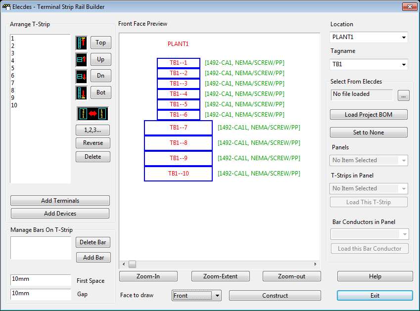
The Elecdes Terminal Strip Rail Builder dialog will then be shown.
Add terminals and/or devices, or load an existing terminal strip.
Reorder components in the terminal strip if required.
Add link bars, if required.
Set the Location and Tagname (at the top of the right hand pane of the dialog).
At the bottom of the dialog, select the . These faces refer to each terminal as it would be placed in a vertical terminal strip in top to bottom orientation (as shown in the preview).
The most appropriate choice for a terminal strip is the front face.
Click to create the terminal strip in the Elecdes drawing. The dialog will close and return to the drawing session, allowing to you place the terminal strip.
The Elecdes dragger will show crosshairs and a bounding box to assist you in placing the terminal strip:
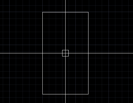
Pressing Tab or o will rotate the terminal strip. The current orientation is shown in the AutoCAD command window. The default orientation is Top to Bottom.
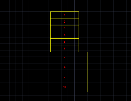
Once you have selected the desired orientation and position, click to place the terminal strip:
Adding Terminals and Devices
Use the and buttons to add terminals and devices. Terminals and devices will be shown in the preview pane of the rail builder dialog once added.
The following dialog allows you to pick terminals and devices to add to the terminal strip:
The first page controls terminal strip numbering, and shows a combobox of recently used terminals/devices.
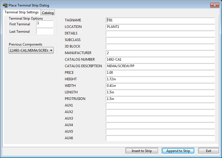
The value starts as 1, and increases automatically the more components you add to your terminal strip.
Enter the number of the last terminal/device (of the selected type) into the text box.
The number of components added will be equal to: Last Terminal - First Terminal + 1
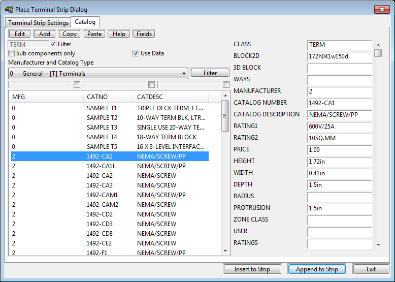
The second page displays the standard catalog, allowing you to browse and select a specific terminal or device to insert.
The BLOCK2D field in the dialog represents the 2D block used for insertion of each terminal. If this field is empty the default 2D block for terminals, VTP2DDEFAULTTERM.dwg, will be used.
For details on attributes used for 2D Panel Layout Components, see Symbol Customisation for 2D Panel Layouts.
Loading an Existing Terminal Strip
You can load existing Terminal Strips from an Elecdes Bill of Materials.
If a project BOM is available, you can click to load it. Alternatively, you can load any other BOM using the (browse) button.
Select a panel from the combo box.
Select a terminal strip from the combo box.
Click .
For more detail, see Selecting Components from Elecdes (in the Paneldes User manual).
Preview Pane
The central pane of the dialog shows a preview of the terminal strip, as viewed from the front when placed top to bottom. The preview can be zoomed in and out.
Note that only outlines of components are shown - full details will only appear when the terminal strip is actually constructed.
Reordering Components in the Terminal Strip
The order of terminals and devices in the strip can be changed by using the buttons to the right of the terminal list. Select the appropriate terminals and devices, then use the following buttons:
Moves the selected components to the top.
Moves the selected components up by one place.
Moves the selected components down by one place.
Moves the selected components to the bottom.
Orders all of the components in ascending numerical order.
Reverses the order of all the components.
Deletes the selected components.
The preview will be updated to reflect any changes.
Adding Link Bars
Link bars can be added to the terminal strip using the controls at the bottom of the left pane of the dialog. Note: Link Bars can only be used when in Front View.
Select the components to bridge from the terminal list.
Click
Select an appropriate bar from the catalog.
Bars will be shown in the preview pane of the main dialog, and added to the terminal strip when it is placed on a drawing.
Bar spacing can be controlled using the and text boxes. Enter a value and units (eg: mm or ").