How to Draw a 2 Line Instrument Loop Circuit
Fundamentals
This function constructs a two-line circuit in any ORTHOGONAL direction and allows periodic selection of terminals and conductor markers to include in/on the two lines.
The purpose of this function is to avoid the time consuming line construction and the terminal and conductor marker positioning PICKS necessary in manual 2 line circuit construction.
During construction of the lines you may construct corners in any ORTHOGONAL direction.
Line crossing
Instrument Loop Autodraw can either cross the lines at certain corners or ensure the lines are uncrossed at all corners.
See Controlling Line crossing.
Procedure
Starting Loop Autodraw
-
Select Construct 2 Line Circuit (Loops) from Elecdes > Drawing Macros menu.
-
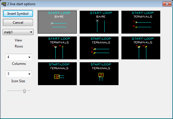
The START METHOD icon menu will be displayed.
Select the start method e.g. 2 rectangular terminals aligned vertically (one above the other) by clicking on the desired icon
-
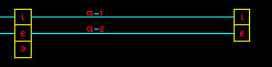
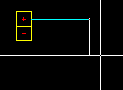
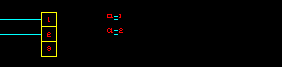
Elecdes will now know the desired appearance of the start of the circuit and request the start point for the UPPERMOST of the 2 lines.
-
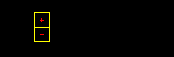
As you have chosen to include terminals at the start of the circuit you will now be asked to provide attribute data for the first (upper) of the two terminals.
For each symbol you will need to confirm the attribute data for the component within the Elecdes Component Dialog, as required during the standard insertion procedure. The name of the terminal will be incremented in the sequence configured by the Naming Sequencer.
-
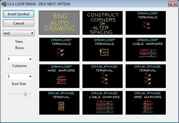
The terminals will be inserted and the COMPONENT SELECTION icon menu will be displayed as shown above.
The components icon menu contains a variety of options for the "next item" in the circuit.
Select the option desired by clicking on the desired icon.
-
Selections from this menu may be repeated until you wish to END the construction. See below for the END option.
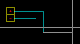
Construct Corners or Alter Spacing
-
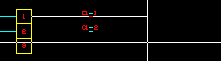
This option allows you to construct 1 or multiple sections of 2 line circuits by drawing in the upper / leftmost line only. These lines may be in any direction, simply PICK the next point of the upper line (left click the mouse to enter these lines) until completed then press <ENTER> to return to the component selection icon menu.

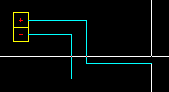
-
Once ENTER is pressed you will be returned to the component selection icon menu.
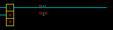
For example:

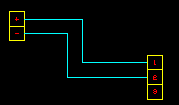
Terminals, wire markers or cable core (conductor) markers
-
At any point during the construction of the loop circuit, you can choose two or three terminals, wire markers or cable core (conductor) markers as the "next item" in your circuit, by clicking on the desired icon.
-
For each symbol you will need to confirm the attribute data of the component within the Elecdes Component Dialog, as required during the standard insertion procedure. The name of the component will be incremented in the sequence configured by the Naming Sequencer.
-
The component selection icon menu will be redisplayed allowing you to select the next circuit option.
END Auto Drawing
-
Select this option to end the circuit. You may end the circuit with two terminals or with bare lines.
-
Elecdes may request the end point for the final lines. Pick the last point if required (upper line):

-
The END METHOD icon menu will be displayed.
Select an end method (2 terminals or bare lines), by clicking on the desired icon.
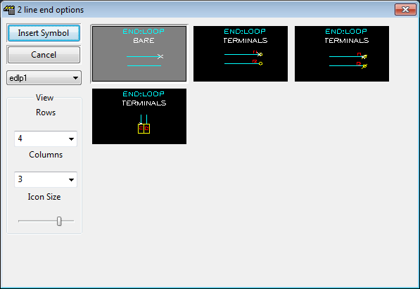
-
If you have chosen to include terminals at the end of the circuit, then you will now be asked to provide attribute data for the first (upper or leftmost) of the two terminals.
For each symbol you will need to confirm the attribute data of the component within the Elecdes Component Dialog, as required during the standard insertion procedure. The name of the terminal will be incremented in the sequence configured by the Naming Sequencer.
-
The lines will be constructed, selected symbol(s) inserted and the function terminated.