Device Symbol: BUSW attribute
General
A special "coded" attribute named "BUSW" has been included with all Elecdes device symbols for the purpose of identifying the terminal arrangement of the symbol's terminals. When a symbol is created you must ensure this code is set correctly for both HI and VI versions of a symbol.
The BUSW attribute is an "invisible constant" attribute. Because it is constant, it exists only as an attribute definition in the original symbol file, not as an editable attribute in each inserted symbol. You must edit the original symbol file to change the BUSW attribute.
To set the BUSW code for a symbol
AutoCAD users:
-
Open the symbol file in AutoCAD.
-
Use the AutoCAD Properties command to alter the "BUSW" attribute definition.
-
Set the DEFAULT attribute setting to one of the predefined codes (see below).
-
Save the symbol.
PowerCAD users:
-
Open the symbol file in PowerCAD.
-
Use the PowerCAD ATTDEDIT command to alter the "BUSW" attribute definition.
-
Set VALUE to one of the predefined codes (see below).
-
Save the symbol.
BUSW Codes
The terminal arrangement defined by the BUSW codes can be one of the predefined arrangements listed below, or (for unusual terminal configurations) can be set to autodetect the terminal positions from the symbol itself.
Autodetected connection positions (BUSW 999 or 998)
The autodetection system is used when the BUSW code of 999 or 998 (reversed 999) is used in the symbol. AutoCAD users can check that the terminal arrangement will be correctly identified by using the Conview utility.
Autodetection supports up to 50 terminals per symbol and the predefined codes support a maximum of 6 terminals per symbol. Both of the systems only support the terminals being positioned on two edges of the symbols, either left and right or top and bottom.
In earlier versions of Elecdes the autodetection system was not available, so a code for a predefined arrangement needed to be used in all cases. Symbols provided with Elecdes generally use a predefined arrangement code instead of autodetection. The autodetection system operates slightly slower than the predefined arrangements when analysing drawings to generate reports from Ebase.
Although the autodetection system enables you to have a more flexible terminal arrangement there are still certain rules and graphical properties that you must adhere to. Refer to Symbol Connectivity Testing. You can expect that you may have to iteratively modify the graphical design of most new symbols to allow EDS to detect the connection points as you intended.
For all new symbols you should use the predefined arrangement whenever possible. The drawings can be analysed faster by the program and the connection points are defined so there is no uncertainty when designing the symbol.
Predefined connection positions
If you are not using the autodetection (999 or 998) system, the BUSW value must be one of the predefined codes for device terminal arrangements that are depicted below:
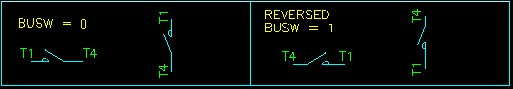
Elecdes will check for connections within 1mm or 1/32" of the two ends of single phase or one line symbols.
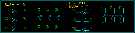
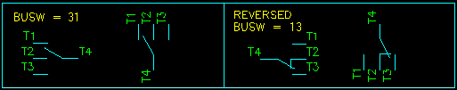
The phases of three phase symbols must be spaced 10mm or 3/8" apart. Elecdes will check for connections within 1mm or 1/32" of the six endpoints of the symbol.
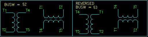
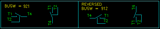
The two conductors for transformer symbols must be 20mm or 3/4" apart. Elecdes will check for connections within 1mm or 1/32" of the four endpoints of the symbol
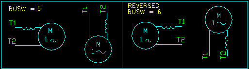
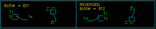
The two conductors for these symbols must be 10mm or 3/8" apart. Elecdes will check for connections within 1mm or 1/32" of the four endpoints of the symbol. The example shows a symbol with connections on only one side of the symbol, the T1 and T2 terminations.
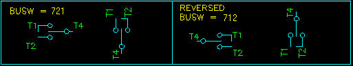
Terminals T1 and T3 must be at least 1.25mm or 3/64" and not more than 11.25mm or 3/8" from terminal T2, which must be on the centre line of the symbol. Elecdes will check for the T2 and T4 connections within 1mm or 1/32" from the endpoints of the centre line of the symbol.
Terminal T2 must be at least 1.25mm or 3/64" and not more than 11.25mm or 3/8" to the right or below terminal T1, which must be on the centre line of the symbol. Elecdes will check for the T1 and T4 connections within 1mm or 1/32" from the endpoints of the centre line of the symbol.
Terminal T1 must be at least 1.25mm or 3/64" and not more than 11.25mm or 3/8" to the left or above terminal T2, which must be on the centre line of the symbol. Elecdes will check for the T2 and T4 connections within 1mm or 1/32" from the endpoints of the centre line of the symbol.
Terminal T1 must be not more than 10mm or 3/8" to the left or above the centre line of the symbol. Terminal T2 must be at least 0.1mm or 1/256" and not more than 10mm or 3/8" to the right or below the centre line of the symbol. Elecdes will check for the T4 connection within 1mm or 1/32" from the endpoint of the centre line of the symbol.
Single Line Diagram Symbols: BUSW = 100 or 101
All single line diagram symbols should have their BUSW code set to 100 for the standard orientation and 101 for reversed symbols. This code informs Elecdes that it does not need to determine terminal information for any connections.
Single line diagram symbols can connect to a conductor line at any point on a rectangular boundary around the entire symbol.
2D Panel Layout components : BUSW = 888
All 2D Panel Layout symbols must have their BUSW code set to 888. This code informs Elecdes that it is not connected to any wire.
For more information on 2D Panel Layout symbols insertion see How to insert 2D Panel Layout symbols.