Symbol Connectivity Testing
General
Device symbols with a BUSW value of 999 or 998 (reversed 999) will be analyzed by Elecdes to determine where the lines (conductors) should connect to the terminals of the symbol. This analysis involves matching the terminal attributes of the symbol to the most likely part of the symbol graphic to which a conductor should be connected.
Although the automatic analysis (autodetection) of the connections is designed to be as intuitive as possible, there could be occasions where the connection points cannot be determined correctly. It is strongly recommended that all BUSW 999 and 998 symbols that are created should be tested using the following procedure.
For symbols that do not use the BUSW value of 999 or 998 you should refer to the BUSW section to determine where the symbol connection points will be. For all BUSW codes other than 999 and 998, the connection points are in up to six pre-determined positions that are specified by the BUSW code – irrespective of the actual symbol graphic and terminal attribute positions. This testing program will run for non-999/998 symbols but shows only summary information about the symbol.
Procedure
-
Start Elecdes.
-
Load the connection autodetection testing utility into the CAD session.
This is done by entering the following command on the command line: (arxload "conview") then press Enter.
(arxload "conview")
and for PowerCAD (the full path to the DLL is required) :
(xload "c:\\eds60\\bin\\conview.dll")
Then press the ENTER key.
Or run the command appload, browse to and load the program file conview.arx.
There should be a success message "Connection View ARX interface loaded" displayed on the command line.
If you will be doing this often, you may wish to add a line to the ACAD.LSP file for Elecdes so that conview.arx is always loaded and ready for use.
-
Open the symbol file to be examined. This must be located in one of the directories that are configured to contain the Elecdes symbol files, e.g. USER_SYMB, MET_SCHE etc.
-
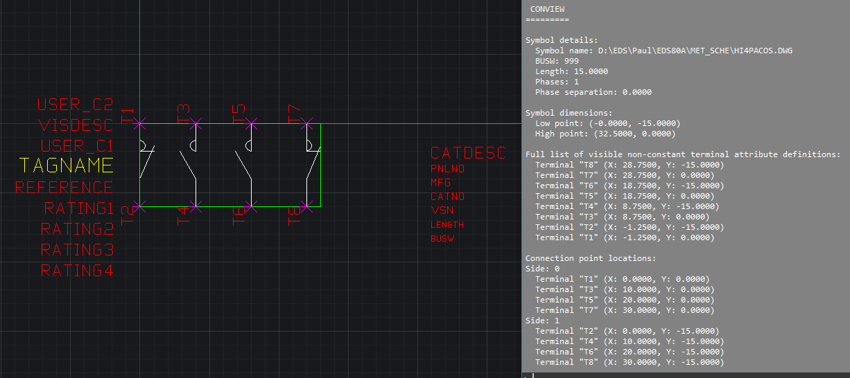
Run the connection autodetection test function. Enter conview in the command line and press ENTER.
The results will be displayed in the command line and also displayed on the drawing.
For BUSW 999 and 998 symbols a cross (X) will be displayed at each located connection point and a line will be drawn from that point to the attribute containing the terminal label for that connection point.
-
If the results are not as desired then the symbol will need to be modified to produce the correct results. See the following section for a description of the procedure used by EDS to analyze connections, this may provide further information on what needs to be modified to obtain the desired results.
Pay particular attention to the section "Symbol details" where the overall symbol parameters are displayed, such as BUSW and LENGTH attributes and, for non-999/998 symbols, the number of conductor phases and phase separation.
Check also the high and low points listed in the section "Symbol dimensions" in case there are unexpected entities making the symbol larger or smaller than expected, and that the distance between the high and low points match the specified LENGTH.
BUSW 999/998 Analysis Overview
The autodetection analysis is described in the following steps. This is the procedure by which EDS determines the connection points of a symbol with a BUSW code of 999 or 998. Comparing these analytical steps to the symbols being tested will help in determining where corrections should be made if necessary.
-
The periphery of the symbol is determined. This is calculated from all of the entities on the symbol, except the attributes.
-
Any circles, lines, points or vertices within 5mm of the periphery of the symbol are considered for potential connection points.
The quadrant of a circle closest to the periphery of the symbol is considered to be its best connection point.
-
Horizontal lines are only considered for connection points on the left and right of the symbol.
-
Vertical lines are only considered for connection points on the top and bottom of the symbol.
-
Lines that extend more than 50% of the distance through the symbol are not considered for potential connection points.
-
Polylines are not considered for potential connection points.
-
For potential horizontal connection points within 1mm vertically of each other, all points except the one nearest the boundary are discarded.
-
For potential vertical connection points within 1mm horizontally of each other, all points except the one nearest the boundary are discarded.
-
The connection point closest to each terminal attribute is now stored, all other potential connection points are discarded.