Setup - Preferences
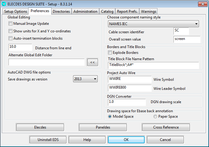
Drawing Space for Back Annotation
Ebase is required to insert components into drawings outside of the CAD package. E.g. Ebase is used for inserting termination blocks and cross-reference annotation. These operations are called "back annotation". With this option you can choose whether the back annotation operations insert symbols into Paper space or Model space on the drawing.
This drawing space back annotation setting does not affect drawing in Elecdes. In Elecdes you should choose either model space or the appropriate layout tab. This setting exists to ensure Ebase matches your choice in Elecdes.
If you choose Paper space, the symbols will be inserted into the paper space layout that was current when the drawing was last saved in AutoCAD.
Configuration for Global Editing
There are three settings that you can change for the Global Editing function.
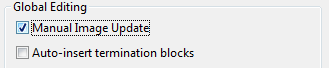
Manual image update
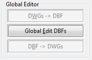
The Global Editing process is a three-step procedure. Firstly, drawing data is extracted to database image files. Secondly it is edited, within the Global Editor, by the user. Finally the modified data is written back to the drawings. By default the first and third steps are done automatically when required. The process is initiated by clicking the Global Edit DBFs button in Ebase.
You can choose to separate the three steps so that the drawing information can be extracted to the image files and written back to the drawings only at your request. If you tick the Manual image update checkbox, the image extraction and reloading buttons on the Ebase dialog will be enabled.
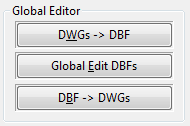
You will need to enable manual image updating if you intend to use a generic database editor (Access / Excel etc.) to edit the image files. The separation of the steps will enable you to extract the data manually, edit it in your database editor and then reload at the point in time that editing is complete.
See General Global Editing Process.
Show units for X and Y co-ordinates
If you tick this setting then Elecdes will put units ( mm or “ ) to the drawing position in the X and Y columns of the image files.
Auto-insert termination blocks
Elecdes termination blocks combine the function of defining:
-
The specification for a crimp/lug for an end of a conductor.
-
The text for a wire label or ferrule for each end of the conductor.
-
The order of the terminations of a wire in the wire report.
If the checkbox is ticked, termination blocks will be inserted automatically near the point where each conductor terminates at a device or discrete terminal. The insertion is done when drawings are updated following Global Editing. This checkbox can also be found on the Global Editor window. The two checkboxes are linked to the same setting.
The distance from the termination point at which the termination block will be inserted is controlled by the following setting.
For more information regarding the use of termination blocks and reporting, see the Ebase and Elecdes manuals.
Distance from line end
This setting controls the distance at which the termination block will be inserted from its termination. By default this is 10mm for metric users and 3/8" for imperial users.
Alternate Global Edit Folder
Global Editing can involve reading, writing and comparing large DBF format and binary files that are normally stored in the same folder as the current EDS project, which may be on a network drive. For improved performance you can choose to store the Global Edit DBF files and your copy of the project cache files in a folder of your choice on your local hard disk drive.
If you wish to keep the Global Edit DBF files and project cache files with the project then leave this box blank.
AutoCAD DWG file options

Save drawings as version
All EDS modules use this setting to determine which version of the AutoCAD DWG format to save your drawings as. Available versions are shown in the drop down, from version 2000 to the highest version supported by your selected CAD Package (from the Setup Options page). The default value is the highest version supported by your selected CAD package.
If you intend to share your drawings with other users who use a different version of AutoCAD, you should select a format less than or equal to the oldest version of AutoCAD in use, in order to maintain compatibility. For example, select "2007" if some users use AutoCAD 2008 and some users use AutoCAD 2012.
Note: Older versions of the AutoCAD DWG format do not support some of the newer AutoCAD features. Newer AutoCAD features that some EDS functions rely on are listed below:
Dynamic Blocks and Parametric Blocks: Supported in version 2007 and later. Used by the Elecdes Terminal Strip Railbuilder and the Elecdes 2D Panel Layout insertion routines.
DGN Converter Scale
When exporting DWGS to Microstation V8 DGN files a scale factor is required. It is set at a default of 1.0 however you can modify this as you desire.
Project Auto Wire
The symbols inserted through the Ebase project auto wire naming function can be configured in the two settings in this section.
Wire Symbol
This is the name of the standard wire marker symbol that will be used in most cases, it is defaulted to WWIRE.
Wire Leader Symbol
This is the name of the wire leader symbol that will be inserted when there is limited space to fit a full sized wire marker. It is defaulted to WWIRE800.
Component Naming Style
Elecdes uses a user programmable formula system to provide a sequence of tag names to use when you insert components. The name sequences are stored in database files that have filenames using the pattern "names*.dbf", where "*" can be any identifying text. You can change your component naming style by choosing a different name sequence file.
The drop down list for the component naming style contains the name sequence files that can be found in the <EDS>\ELECDES directory. Change the selection in the list to change the naming style.
By default, NAMES ANSI is selected when you use imperial units and NAMES IEC is selected when you use metric units.
If you add your own name sequence files with correct "names*.dbf" filenames, they will also be available in this drop down list.
Click to open and edit the selected name sequence file in Database Editor.
See Naming Sequencer.
Cable Screens
EDS identifies cable screens (shields) by the text entered in the Cable Screen Identifier textbox. Any cable core (conductor) starting or ending with the Cable Screen Identifier will be designated as a screen. The default value is "SC" (for Screen) in a metric configuration, or "SH" (for Shield) in an imperial configuration.
Overall screen value is the text EDS will use when inserting an overall screen for a cable. The default value is "screen" (in metric) or "shield" (in imperial).
See also: Cable Screen Configuration (Wiring Diagram Generator)
See also: Instrument Builder, Device Builder (Instrument Manager)
See also: Predefined naming sequences
Borders and Title Blocks
Explode border blocks after insertion
Explode Borders
You can choose to have border blocks exploded after they are inserted by the Elecdes border insertion function.
This option is selected by default when EDS is configured for imperial units.
The sample imperial borders include a selection of borders with zones inserted for rung number cross-referencing. When the border is exploded, the zones become individual blocks in the Elecdes drawing. They are then used by the cross-referencing functions.
For more information regarding cross-referencing coils and contacts, see the Ebase and Elecdes manuals.
Drawing Index Block Pattern
In the Title Block File Name Pattern edit box, you may type one or more file name "patterns" that will uniquely identify title block symbols on your drawings. The information contained in the attributes of matching title block symbols will be extracted to produce the Ebase Drawing Index report.
Valid Title Blocks are detected by matching the block file names to the specified pattern(s), using the Specmatch system.
You may include wildcard characters in the pattern:
-
"*" will match any number of letters or digits.
-
"?" will match any single letter or digit.
-
"@" will match one or more letters.
-
"#" will match one or more digits.
If you have title blocks that have differing block file names, e.g. for different customers, then you can enter multiple patterns into the box, separating them with semicolons ';' as shown in the picture.
The default pattern, "TitleBlock*", will match any of the sample title blocks supplied with EDS. The sample title block names are "TitleBlock_A.DWG" ... "TitleBlock_E.DWG" for imperial users and "TitleBlock_A0.DWG" ... "TitleBlock_A4.DWG" for metric users.
Links to Elecdes, Paneldes and Cross-Reference Preferences
These three buttons display the preferences for Elecdes, Paneldes and Cross-Referencing.
Refer to the appropriate customisation documents for instructions on these preferences.