How to Assign Components to an Output Diagram
General
The data that appears on the output diagrams comes from the components, usually instruments, assigned or linked to the output diagram. Multiple components can be shown on a single diagram. For example a tabular datasheet or three loops on one loop diagram.
Components can be moved from one output diagram to another of the same type.
The components are linked to the output diagram by the relational linking system in Instrument Manager.
Procedure
A component may be assigned to an output diagram using any of the following procedures:
-
Drag and Drop components onto an output diagram entry in the tree.
-
"Add existing" component from the pop-up menu for the output diagram item.
-
"Copy" components and "Paste Link" onto the output diagram.
For more information see Linking Components.
Arrangement of multiple components on an output diagram
The order that multiple components appear on a single diagram can be changed if necessary by manually assigning a number that represents the position for each component assigned to the diagram. Enter increasing numbers into the appropriate *_Order column of each component tag record.
-
Use DS_Order to arrange components on datasheets.
-
Use HU_Order to arrange components on hook-up diagrams.
-
Use LP_Order to arrange instruments on simple, automatically drawn loop diagrams.
-
Ordering is not necessary for terminal strip and wiring diagrams because the individual components are arranged using the EDS Wiring Diagram Generator.
-
Ordering by a column is not necessary for custom loop diagrams because each component is assigned to a specific link on the custom loop diagram, as described below.
Loop diagrams
Assigning components to simple automatically drawn loop diagrams
For a simple automatically drawn loop diagram, only the primary instrument should be assigned to the loop diagram. The remainder of the loop circuit is determined automatically by Instrument Manager.
If more than one instrument is assigned to the loop diagram then a separate loop circuit will be drawn for each instrument on the same diagram and arranged vertically.
Assigning components to custom loop diagrams
If the loop makes use of a custom loop template, then all of the components (instruments, devices, terminal strips, wires, cables and user types) must be assigned to the loop diagram. For a custom loop diagram, Instrument Manager does not trace the circuit and draw the loop automatically.
You should make use of hints on your custom loop links so that you do not need to assign each of the components to the custom loop manually. In an ideal template there will be sufficient hints so that you assign only the instrument(s) and Instrument Manager will be able to derive all of the other components to assign to the loop diagram from hints.
-
Assigning a component to a custom loop diagram is initiated in the same manner as it is for other diagrams, i.e. by Drag and Drop, "Add existing" or Copy and Paste. See Linking Components.
-
You must then choose the link on the custom loop diagram to which the component should be assigned.
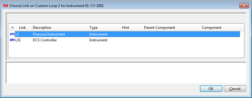
The list of links will be filtered to include only those that require a component of the type you are attempting to assign to the loop diagram. The description for each link is user-defined in the template to identify each link.
If there is only one suitable link for the type of component you are attempting to assign then this step (choosing from a list of links) will be skipped.
-
Choose the desired link from the list, then click [Ok].
-
If the custom loop links contain hints (which is highly recommended), then other links will be filled automatically if Instrument Manager can now determine the correct component from your recent manual assignment and the specified hints.
-
If all of the custom loop links could be filled then the "Status" column of the custom loop will show "Complete". If one or more custom loop link remains empty then the "Status" column will show "Loop items missing".
When a component is manually assigned to a custom loop link, the D1 (loop diagram) link in the component's record is set to the custom loop. If the assignment is made by a hinted link then it will only set the D1 link in the component's record if the D1 link is currently empty. This link is used for the menu entry .
Managing component assignment to a custom loop
You may view and change the assignment of components to a custom loop from a single dialog window.
-
Right click on the custom loop diagram record and choose "Configure Loop Components".
The window shows a list of the component links available on the custom loop, the description given to each link from the custom loop template, and the names of any components that have already been assigned to links.
-
Choose a link and click "Add" to choose a component to assign to that link.
You can also double-click the entry to run the Add function.
The list of components is filtered according to the component type specified for the link.
Choose the desired component and click "Ok" to assign it to the selected link.
When the selected link has an assigned component, a preview of the circuit for the component will be displayed at the bottom of the window. The preview shows whatever Instrument Manager can automatically determine of the circuit connected to the assigned component.
-
Choose one or more links and click "Remove" to remove a component assignment from a link.
Refreshing hinted assignments
New components or connections may mean that new assignments can be made to the custom loop diagrams. Changes to the components and connections between the terminals and conductors may mean that the previous assignments to custom loop diagrams are now incorrect.
If you have designed your custom loop templates with hints then you can have Instrument Manager "refresh" the assignments that should be made automatically by Instrument Manager from the hints.
-
Select one custom loop diagram from the tree, or select multiple custom loop diagrams from the list in list view, that you wish to refresh.
-
Right click with the mouse pointer over the selected diagrams.
-
Select "Refresh component assignments from hinted links" from the pop-up menu.
-
Instrument Manager will check for hints that it can resolve from the current project database contents to assign components to the custom loop(s).
-
If a hint for a link cannot be resolved but you have previously manually assigned a component to the link, then that manual assignment will remain.
This is useful for loops that do not entirely suit the templates, such that some hints cannot be resolved and you must assign those components manually. You will not loose those manual assignments by refreshing the hinted loop assignments.
-
If all of the custom loop links could be filled then the "Status" column of the custom loop will show "Complete". If one or more custom loop link remains empty then the "Status" column will show "Loop items missing".
Custom loop hints will also be refreshed automatically and quietly as the first step when generating the output diagrams.
For more information about using custom loops, see Custom Loop Diagram Templates.
See also:
Add Output Diagrams to the Database