Output Diagrams
Output diagrams are the main outputs of the Instrument Manager package. There are four types of output diagram: datasheet, loop diagram, hook-up diagram and terminal strip diagram.
Datasheets are Microsoft Excel XLS, XLSX, XLSM or XLSB format files. Loop, hook-up and terminal strip diagrams are AutoCAD DWG format files.
The diagrams are generated from output diagram templates that have been populated with data from the records of the project database. The records used to populate the diagrams are obtained from the components that are assigned or linked to the output diagram.
Output diagrams each have their own record in the project database and they each have their own entry in the category tree, under the Output Diagrams category.
Output diagram types
Datasheets
Datasheets are Microsoft Excel XLS, XLSX, XLSM or XLSB format spreadsheets. Datasheets are used to document the specifications for components and conductors stored in the project database.
A datasheet may be used to edit the specification of an instrument or device from the project database:
See Also: Component Operations, Edit with Excel.
Loop Diagrams
Loop diagrams are AutoCAD DWG format drawings.
Simple twin conductor loop circuits can be determined automatically from the electrical connections made to the primary instrument. Instrument Manager creates the final diagram by inserting a loop component template for each component in the circuit and drawing the conductors between the components.
For more complex instrument loops, a specific template may be designed that contains all of the components on the loop: a user-defined custom loop diagram.
Hook-up Diagrams
Hook-up diagrams are AutoCAD DWG format drawings that show the connection details and mounting hardware for components.
Materials shown on a hook-up diagram can be included in the EDS materials reports, see Output Diagram Templates.
Terminal Strip and Wiring Diagrams
Terminal strip and wiring diagrams are generated to show the wiring details for terminal strips, devices and instruments configured in the project database. They are AutoCAD DWG format drawings.
The EDS Wiring Diagram module performs the generation of terminal strip and wiring diagrams at the request of Instrument Manager. When a terminal strip diagram is generated from Instrument Manager, the Elecdes program and the Wiring Diagram Generator module will be started. The assigned terminal strips and devices will be automatically selected in the device list, and you can immediately click the [Generate Wiring Diagrams] button to draw the diagram.
Output Diagram File Locations
The location of the generated files is usually the specified default output directory for that type of diagram. For a new Instrument Manager project, all of the default output directories will be set to the directory that contains the project. You can change the default output directories in the Project Preferences.
If you specify a full path with the file name for any individual output diagram, then the diagram will be created in the directory that you have specified.
Output Diagram Templates
The template that is used to create an output diagram is set when the record for the diagram is created in the project database. When a diagram object is created the template must be chosen from a list of available templates.
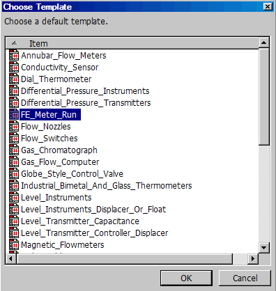
New templates can be added to the list by adding to the appropriate template folder.
The template for an output diagram can be reselected at any time by right clicking on the diagram and selecting "Pick Template" from the pop-up menu.
For information about templates for output diagrams, see Output Diagram Templates.
See also:
Add Output Diagrams to the Database
Generate, View and Print Output Diagrams