How to Add Output Diagrams to the Database
General
Output diagrams each have their own record in the project database and they each have their own entry in the category tree, under the category Output Diagrams. After an output diagram record has been created in the database you can link components to the diagram. These components will then be shown on that diagram when the output diagram is "generated".
When you create new components, you will be asked if you wish to create an output diagram automatically for each component.
Add components to the database
Assign Components to Output Diagrams
Create output diagrams for a group of components
In one operation an output diagram can be created for one or more components and each component linked immediately to its new diagram. This is particularly suitable when each diagram will show only one component.
-
Select one component from the tree, or select multiple components from the list (in list view) for which you wish to create an output diagram.
-
Right click with the mouse pointer over the selected component or components.
-
Select "Copy" from the pop-up menu.
-
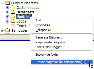
Right click on the output diagram folder for the type of diagram that you wish to create for each component.
-
Select "Create diagrams for components (#)" from the pop-up menu. The number in brackets lets you know how many components were selected and therefore how many diagrams will be created.
-
You can also Drag one or more components from the tree or list and Drop them directly on the output diagram folder in the tree. This achieves the same as the procedure above.
-
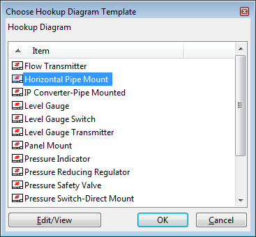
If the selected component type is not configured to have a default template for this type of diagram, then you will be asked to choose the template for the new diagram.
You will also be asked if that template should be made the default for the selected component type for creating future diagrams.
You can still change the template for an output diagram after it has been created.
-
A diagram will be created for each of the selected components.
The name of each diagram will be set automatically, by default with a prefix, e.g. "HOOKUP-", followed by the component name.
Each component will be shown as a link under its new diagram in the tree.
Create an empty output diagram
If you will be showing multiple components on each diagram then you can create the diagram itself, then assign the desired components to the new empty diagram in a separate operation.
-
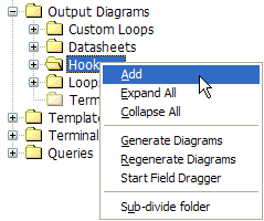
Right click the appropriate output diagram folder in the tree.
-
Select "Add" from the popup menu.
-
Choose the template for this diagram.
You can still change the template for an output diagram after it has been created.
-
Enter a name for the new output diagram.
-
A new empty diagram will be created.
You may now assign one or more components to be shown on this diagram.
Terminal strip and wiring diagrams
The terminal strip diagram category can also be used for wiring diagrams for devices or instruments. If you wish to create a wiring diagram for a device or instrument, follow the instructions above to create a diagram and choose the "Terminal Strip Diagrams" category. Assign device or instrument components to the new diagram.
Loop diagrams
Note that there are two types of loop diagram: simple, automatically drawn loop diagrams and custom loop diagrams.
-
Simple automatically drawn loop diagrams are all created in the folder "Loops" under "Output Diagrams" and their records are all stored in the same table.
-
Custom loop diagrams have user-defined folder names under "Output Diagrams" and there will usually be one folder and one table for each different custom loop template.
You choose the type of loop diagram by choosing the appropriate folder.
See also:
Generate, View and Print Output Diagrams
Assign Components to Output Diagrams