Route Connections
General
Paneldes routing functions examine the route lines and components of your model. After collating all of the route information, the routing functions will search all of the routes on your model for APPROXIMATE connection. This produces one or several networks of connected raceway routes. Paneldes then examines these networks for an APPROXIMATE connection to devices and panels. When a network is fully connected, to all of the components, Paneldes then establishes the possible routes between components for cable and wire placement. These connections are used by Paneldes as the basis for the automatic routing procedures. Wire setup also defines a TRIMMING length allowance for wires.
APPROXIMATE connection
Paneldes searches a region around any route line segment for other route line segments, which may be connected. A few basic rules are applied to route segments within the region and connections between routes are made or rejected. Paneldes will search a region around any component for a route to feed that component. APPROXIMATE connection describes the process of connecting routes to other routes (and components) that do not actually touch each other, but do come close enough to assume connection.
Tuning the connection distances
The size of the regions will affect processing in two ways:
-
Too small a connection distance may cause the routing software to miss connections.
-
Too large a connection distance will find extra connections and take a longer time to process. Larger connection distances may also find incorrect connections, which will remove accuracy from route length analysis. Wires could JUMP from one duct to another without travelling through any intermediate ducts.
You must ensure your distances are set to avoid jumps and missed connections. Use the wire viewing tools to check this.
Connection distances
You must decide before modelling, the criteria for connection (approximate) and build your model to suit. Decide upon the settings to use before making the model. Make the settings before route optimisation.
Paneldes can suggest some of these connection distances and settings automatically. See Automatically Suggested Connection Settings.
NOTE: The full list of connection distances and other parameters can be modified only in the Paneldes preferences. See How to configure routing settings. The route optimisation function provides you the option to change a small number of these settings during the execution of the function.
For Cable Routing
| Setting Name | Description |
|---|---|
| Route to panel or device | For plant trays etc. to connect to panels and field devices or instruments. |
| Route to route end | For any two plant route lines meeting at endpoints. |
| Route to route mid point | For two plant routes intersecting anywhere along their lengths. |
| Conduit to trench | Conduit endpoints sufficiently close to a trench route line. |
| Maximum alternative route length | The maximum distance of an alternative route length. This limits the length of the route Paneldes will take when forced to take an alternative route because of route over-filling. |
|
Cable Trimming Length Additional Trim Wastage (%) |
Added to each length of cable to allow for some extra length over and above the exact length (e.g. stress relief, termination, trimming, cornering etc.). The variables can be either a set size (e.g. 2m) or a percentage (e.g. 10%). The additional trim wastage variable allows a mix of set value and %. |
Other Cabling rules
-
Conduits will not connect at mid points.
For Wire Routing
| Setting Name | Description |
|---|---|
| Panel route to device | For ducts etc. to connect to panel mounted devices, terminal-strips etc. |
| Route to route end | For any two panel route lines meeting at endpoints. |
| Route to route mid Point | For two panel routes intersecting anywhere along their lengths. |
| Link length | unused |
| Wire trimming length | Added to each length of wire, between two terminations, to allow for wire stripping and any other margins you may require, over and above the exact length between the chosen two terminations (e.g. stress relief etc.). |
Other Wiring rules
-
Trenches may not be used in panel models.
Snug Fitted Conduit
Conduits which have an end to end connection to another conduit will not allow cables to "leak" from the junction provided the connection is a snug fit connection. To Paneldes, the junction becomes sealed as if it was a continuous pipe.
A snug fit connection is made where:
-
The radii of the two conduits are within 10% of the same value.
-
The end points of the route lines of the two conduits are not separated by more than the Snug fit distance.
Other Snug Fitted Raceway
Raceway other than conduit (i.e. tray, ducting, and trench) may also be considered to be snug fitted. However, a snug fit between these types is not as restricted as a snug fit between segments of conduit.
The restriction is that a snug fitted segment pair cannot join to the segments of another snug fitted segment pair. Non-snug fitted segments may connect to a pair of snug fitted segments. These non-snug fitted segments therefore allow cables to enter or leave the junction.
This less restricted snug fitting prevents cross-connection between close parallel runs of raceway that have junctions in close proximity. This feature is generally aimed at parallel runs of tray stacked above each other.
The restrictions do not apply where runs of raceway that have junctions in close proximity however are crossing each other and not parallel.
A snug fit connection is made where:
-
The two segments are both of the same type (e.g. both tray).
-
The end points of the route lines of the two segments are not separated by more than the Snug fit distance.
You can change the Snug fit distance in the Paneldes preferences. See How to Configure the Wire and Cable Routing Settings.
Very short segments and snug fitting
The Snug fit distance effectively defines a minimum size for raceway segments. The snug fit distance should be set to be shorter than your shortest segment length, especially fittings.
The analysis of connectivity of raceway segments will attempt to discard a connection that jumps across a small intermediary segment that makes that same connection. However, if everthing is within a very short distance and the jumping connection is short enough to be a snug fit, then it is not discarded. This means that the intermediary segment can still be jumped, so it will be missing from the final routes. This is most likely to be seen with riser segments for flexible cables that have a tight bend radius and low side walls, resulting in a small overall length.
Incompatible power numbers prevent connection
Route segments with no overlap in power numbers will be prevented from connecting together, irrespective of the distance between them.
You can use point separated power numbers to prevent connection between segments that have the same primary power numbers. See Power Numbers for Raceway, Cables and Wires for more information.
Thus if two segments appear to be joined correctly in the model yet no route can be found through that junction, the segments may not have any common power numbers.
Connections cannot "double back"
If a connection between two route line segments would make a sharp angle of more than 170 degrees, then this connection is rejected.
For example, in a ductbank a nearly parallel conduit will double back by ~180 degrees, which is > 170, so connections between parallel conduits will be rejected.
You can change the 170 degree Double back angle used for this test. See How to Configure the Wire and Cable Routing Settings.
Closest connections to devices or panels determine optimum route
The Paneldes route optimisation functions can find more than one route between two components. Where more than one route is found, the best route is considered to be the one that has the shortest total connection distance to the two devices or panels from their respective final two route segments.
This assists the route optimisation function to use the most obvious route segment when multiple segments are within the specified Route to panel or device setting.
Forcing the connection to devices and panels
You can dictate exactly which route line segment will be the first connection from a selected device or panel. If your design requires that a specific connection, which does not fit the Paneldes rules, is to be made from a device or panel, you can use the function Select Connection Tray to ensure the correct connection is made.
Connection to distant devices and panels
Devices have a fall-back condition for connection. If there are no route line segments found within the specified connection distance, then the router will find the closest raceway segment ENDPOINT, outside of the set connection distance, that has a suitable power value and availability. The router will then find all suitable raceway segments within the same set connection distance of that segment ENDPOINT. These found segments will all be tested for a suitable route. By this method the router is finding the "nearest cloud" of suitable segments for the cable. This will help in circumstances where your model does not have enough raceway segments in close proximity to a panel or device.
Paneldes will write a warning in the route report indicating that the device connection was outside of the specified limit.
It is not necessary to construct raceway to the absolute destination. Field routing enables Paneldes to complete the route without a full network of raceway.
Modular Sub-Components and Routing
If you have multiple devices with the same tagname and location on your model, then Paneldes will route to the device with the largest dimensions out of the group of duplicates. Paneldes will also write a warning in the route report indicating that this action was taken.
Best duct for a device (wires only)
Generally during wire routing, the closest duct in the preferred direction will be used to connect to a terminal of a device.
If there is no preferred direction OR the closest duct in the preferred direction is not close enough (route to device/panel distance), then the closest duct, in any direction, within the required connection distance will be used.
The preferred direction for the connection from a terminal to a duct can be specified in the device terminal catalogs (CATX).
Best duct for a discrete terminal (wires only)
Generally during wire routing, a discrete terminal in a terminal strip can connect to any duct that is within the connection distance.
If the terminal is polarised then Paneldes will use the closest duct in the direction appropriate to the side specified for the connection in the FromToWire report (TERMSIDE_A/B columns). Connections with SIDE1 will connect to a duct above the terminal. Connections with SIDE2 will connect to a duct below the terminal. Above and below refer to an axis aligned with the HEIGHT dimension of the terminal.
Connect to closest duct
There is a checkbox in the Paneldes preferences : Wire and Cable Routing->Force connect to closest duct. This checkbox will ensure that the closest duct to any terminal (for wiring) or the closest tray to any panel (for cabling) will be selected by the router. This setting overrides the other criteria.
Connections Between Terminals on the Same Device
When connecting two terminals on the same device, Paneldes will use the device terminal, CATX, catalog data for the device to determine how the connection will be made. If the device has a value in the LINK_LEN field of its CATX catalog, the link length will be used to make a decision about the method of connection to use. The following formula is used to determine whether the wire should travel directly between the terminals OR from the first terminal to a duct and back to the other terminal.
Calculated Link Length = Horizontal distance from terminal A to terminal B
+
Vertical distance from terminal A to terminal B
If this Calculated Link Length value is larger than the LINK_LEN value for the device then the wire will connect from the first terminal to a duct and back to the second terminal. If however the Calculated Link Length is smaller than LINK_LEN then the terminals will be directly connected.
The picture on the left shows the terminal to duct and back method and the picture on the right shows the direct terminal to terminal connection method.
| Terminal to Duct to Terminal | Terminal to Terminal |
|---|---|
 | 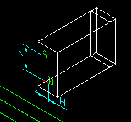 |
Note that trim length will always be added to the route length irrespective of the connection method. This trimming length is configured in the Paneldes preferences.
See Also...
Automatically suggested connection settings
How to check the raceway connections in your model
How to route to a device with undefined raceway
How to force the first connection for a route
How to tune your model for wire and cable routing