Loop Diagram Preferences
General
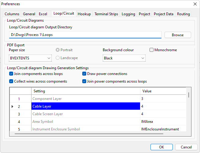
On the Loop preferences page you can specify options directly related to creating instrument loop diagrams. You can specify the directories or file system folders in which Instrument Manager can find the files used to create loop diagrams. You can specify the default template that will be used to represent each type of component on a loop diagram. You can specify the positional information for arranging the components on the loop diagram.
Default Loop Diagram Output Directory
Enter the directory in which loop diagrams will be created. If you enter a new directory name it will be created automatically. Click the [Browse] button to choose an existing directory.
For a new project, this will initially be set to the directory containing the project database.
PDF Export
You can choose the orientation of your exported PDFs to be portrait OR landscape, choose the page size and choose whether to use a black or white background colour.
Loop Generation Settings: Join components across loops
By default, each instrument on a loop diagram has default signal lines traversing the loop diagram, through multiple intermediate stages (JBs, terminal strips etc), ending at the controlling device (e.g. the PLC). It is often the case that a designer places multiple related instruments on the same sheet and these instruments and their signal lines happen to share some intermediate stages.
By default, These shared “common” intermediate stages will draw separately on an Instrument Manager auto-loop.
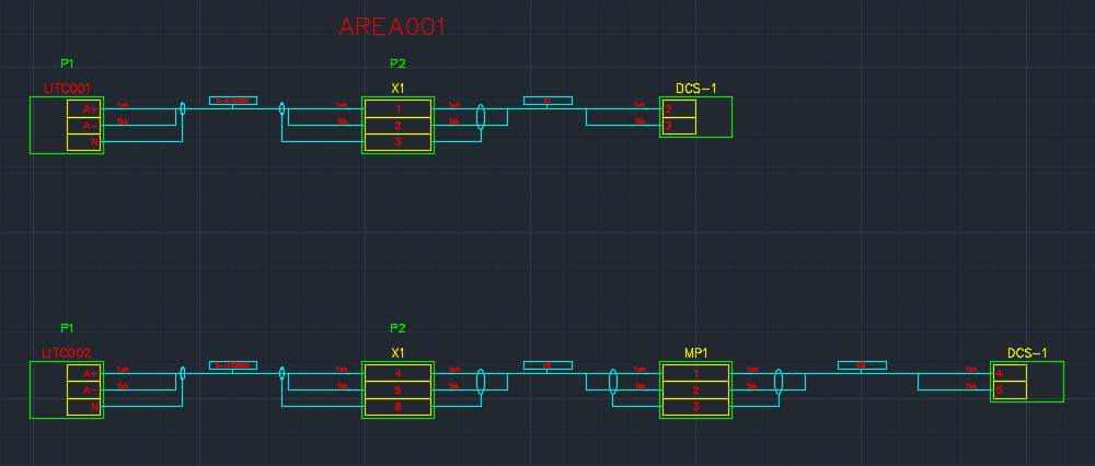
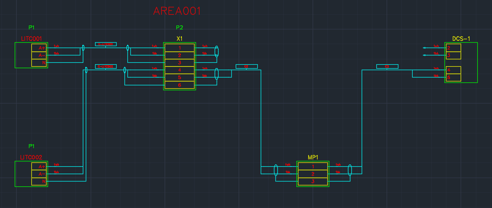
Enabling this preferences option, will cause the loop drawer to draw "common" intermediate stages as a single component if possible.
Rules:
For these components to join, the two circuits in the Loop Diagram containing the common component must be in adjacent rows. To assist, the Loop Drawer will automatically try to reorder the circuit rows to allow for common item joining.
The common components must be in the same stage positions (columns). To assist, the Loop Drawer will automatically try to align the components in the circuit columns to maximize common item joining.
Notes:
Where the Loop Drawer cannot join components, the Loop Drawer will attempt to align components based on the following properties being common (highest priority to lowest priority):
- Components in the same Enclosure and of the same type
- Components of the same type
- Components in the same Enclosure
- Components in the same Area
- Any "common" stages from "power connection" circuits will only join with the stages from the instrument's signal circuit, if the "Join power components across loops" is also enabled. For more information, see Draw power connections and Join power components across loops sections below.
Loop Generation Settings: Collect wires across components
This setting is only available when the "Join components across loops" setting is enabled.
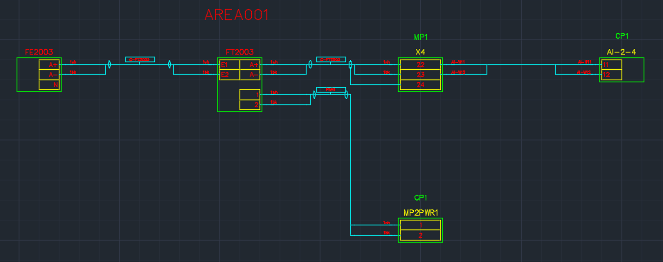
When enabled, all the wires between two stage positions, across all the loop circuits, get collected and drawn as a bundle.
Loop Generation Settings: Draw power connections
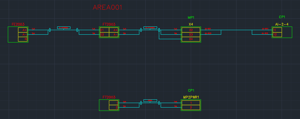
Instruments are typically “loop-powered”, from power available on the signal line OR an instrument may need a separate power supply cable and has terminals for the connection of this cable. When an instrument has a separate power supply cable, it is often desirable to show this connection on your loop diagram adjacent to the instrument’s signal loop.
This setting, when enabled, will cause Instrument Manager to detect and draw any “power connection” belonging the instrument adjacent to the instrument’s signal loop.
To add a power connection to an instrument, you must create a terminal group, for the instrument, with prefix of "IP" or "OP". "IP" or "OP" will dictate the group type as a “power connection” for that terminal group.
The Loop drawing system will create a separate “power connection” loop circuit when it encounters a power terminal group.
Auto Loop “Anchor points” can be used for positioning a “power connection” circuit on your loop. See Anchor points for templates for simple automatically drawn loops.
Loop Generation Settings: Join power components across loops
This setting is only available when the "Join components across loops" and "Draw power connections" setting is enabled.
This setting, when enabled, will cause the Loop Drawer to join "common" stages from the "power connection" circuit with the stages from the instrument's signal circuits.
Loop Generation Settings: Templates and Positional information
The loop generation settings include general settings, template defaults, and template spacing defaults. The default template can be overridden on a per-component basis. The default position can be overridden on a per-template basis.
| Loop Generation Setting: | Description: |
|---|---|
| Component Layer | Layer on which the component box outline is drawn. |
| Cable Layer | Layer on which the cable is drawn. |
| Cable Screen Layer | Layer on which the screen is drawn. |
| Area Symbol | Default symbol for an area. |
| Instrument Enclosure Symbol | Default symbol for an enclosure of an instrument. |
| Device Enclosure Symbol | Default symbol for an enclosure of a device. |
| Terminal Strip Enclosure Symbol | Default symbol for an enclosure of a terminal strip. |
| Instrument Symbol | Default symbol for an instrument. |
| Two-sided Instrument Symbol | Default symbol for an instrument connected on both sides. |
| Device Symbol | Default symbol for a device. |
| Terminal Strip Symbol | Default symbol for a terminal strip. |
| Terminal Strip Terminal Symbol | Default symbol for a terminal from a terminal strip. |
| Terminal Strip Break Symbol | Symbol for a terminal strip break. |
| Instrument Terminal Input Symbol | Default symbol for a terminal on the left side of an instrument. |
| Instrument Terminal Output Symbol | Default symbol for a terminal on the right side of an instrument. |
| Instrument Terminal Through Symbol | Default symbol for a terminal connected on both sides of an instrument. |
| Device Terminal Input Symbol | Default symbol for a terminal on the left side of a device. |
| Device Terminal Output Symbol | Default symbol for a terminal on the right side of a device. |
| Device Terminal Through Symbol | Default symbol for a terminal connected on both sides of a device. |
| I/O Channel Symbol | Default symbol for an I/O channel ( A terminal group in a PLC ). |
| Cable Symbol | Default symbol for a cable. |
| Main Conductor Input Symbol | Default symbol for a conductor connected into the left of a component. |
| Main Conductor Output Symbol | Default symbol for a conductor connected out from the right of a component. |
| Secondary Conductor Input Symbol | Default symbol for a conductor branching into the left of a component. |
| Secondary Conductor Output Symbol | Default symbol for a conductor branching out from the right of a component. |
| Core Main Conductor Input Symbol | Default symbol for a core connected into the left of a component. |
| Core Main Conductor Output Symbol | Default symbol for a core connected out from the right of a component. |
| Core Open Circuit Input Symbol | Default symbol for a core connected into the left of a component, disconnected on the other end. |
| Core Open Circuit Output Symbol | Default symbol for a core connected out from the right of a component, disconnected on the other end. |
| Core External Input Symbol | Default symbol for a core connected into the left of a component, connected externally on the other end. |
| Core External Output Symbol | Default symbol for a core connected out from the right of a component, connected externally on the other end. |
| Wire Main Conductor Input Symbol | Default symbol for a wire connected into the left of a component. |
| Wire Main Conductor Output Symbol | Default symbol for a wire connected out from the right of a component. |
| Wire Open Circuit Input Symbol | Default symbol for a wire connected into the left of a component, disconnected on the other end. |
| Wire Open Circuit Output Symbol | Default symbol for a wire connected out from the right of a component, disconnected on the other end. |
| Wire External Input Symbol | Default symbol for a wire connected into the left of a component, connected externally on the other end. |
| Wire External Output Symbol | Default symbol for a wire connected out from the right of a component, connected externally on the other end. |
| Wire Link Blob Symbol | Default symbol for a wire connected as a link between two terminals of a component. |
| Screen Symbol | Default symbol for a screen or shield for a pair. |
| Downward Screen Symbol | Default symbol for a screen or shield for a pair, facing downwards. |
| Screen Open Circuit Symbol | Default symbol for a screen or shield for a pair, disconnected on the other end. |
| Triad Screen Symbol | Default symbol for a screen or shield for a triad. |
| Downward Triad Screen Symbol | Default symbol for a screen or shield for a triad, facing downwards. |
| Triad Screen Open Circuit Symbol | Default symbol for a screen or shield for a triad, disconnected on the other end. |
| Overall Screen Symbol | Default symbol for an overall screen or shield. |
| Overall Screen Open Circuit Symbol | Default symbol for an overall screen or shield, disconnected on the other end. |
| Loop Generation Setting: | Description: |
|---|---|
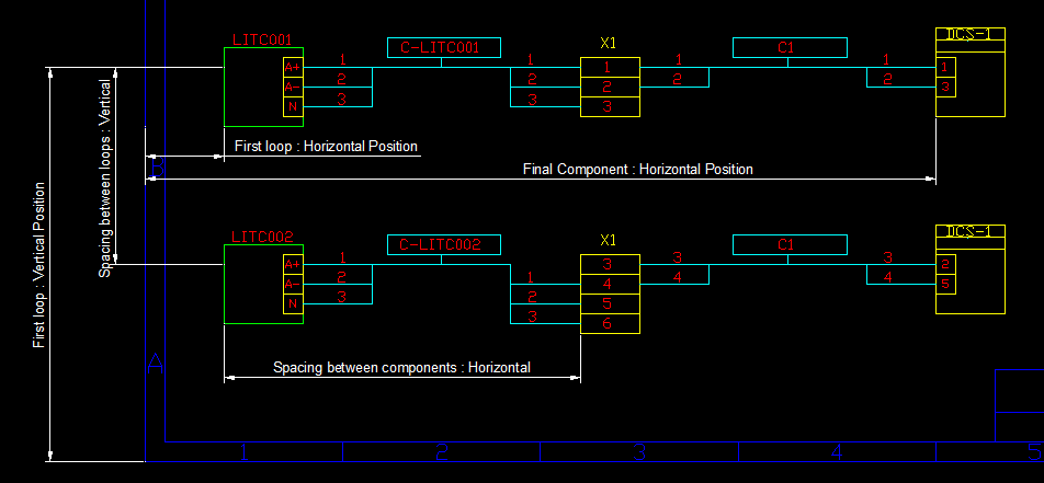
| First loop: Horizontal position | Horizontal position of the first instrument of the first loop. |
| First loop: Vertical position | Vertical position of the first instrument of the first loop. |
| Final Component: Horizontal position | Optional value to fix the horizontal position for the final component in any loop. |
| Spacing between components: Horizontal | Horizontal distance between adjacent connected components in a circuit. |
| Spacing between loops: Vertical | Vertical distance between two loop circuits on the same diagram. |
| Gutter for instrument box: Horizontal | Horizontal distance between the terminals and the component box drawn for an instrument. |
| Gutter for instrument box: Vertical | Vertical distance between the terminals and the component box drawn for an instrument. |
| Gutter for device box: Horizontal | Horizontal distance between the terminals and the component box drawn for a device. |
| Gutter for device box: Vertical | Vertical distance between the terminals and the component box drawn for a device. |
| Gutter for terminal strip box: Horizontal | Horizontal distance between the terminals and the component box drawn for a terminal strip. |
| Gutter for terminal strip box: Vertical | Vertical distance between the terminals and the component box drawn for a terminal strip. |
| Spacing between terminals in two-sided instruments: Horizontal | Horizontal distance between input and output terminals on an instrument with connected on both sides. |
| Spacing between link wires: Horizontal | Horizontal distance between the lines for different link wires joining terminals on a terminal strip. |
| Spacing - cable lines: Horizontal | Horizontal distance between the lines for different cable when using slots to avoid overlaps. |
| Area: Horiz offset | Horizontal offset from the position of the component stage at which to insert the area symbol. |
| Area: Vert offset | Vertical offset from the position of the component stage at which to insert the area symbol. |

| Loop Generation Setting: | Description: |
|---|---|
| Enclosure of device: Horiz offset | Horizontal offset from the position of the component stage at which to insert the enclosure symbol of a device. |
| Enclosure of device: Vert offset | Vertical offset from the position of the component stage at which to insert the enclosure symbol of a device. |
| Enclosure of instrument: Horiz offset | Horizontal offset from the position of the component stage at which to insert the enclosure symbol of an instrument. |
| Enclosure of instrument: Vert offset | Vertical offset from the position of the component stage at which to insert the enclosure symbol of an instrument. |
| Enclosure of terminal strip: Horiz offset | Horizontal offset from the position of the component stage at which to insert the enclosure symbol of a terminal strip. |
| Enclosure of terminal strip: Vert offset | Vertical offset from the position of the component stage at which to insert the enclosure symbol of a terminal strip. |
| Loop Generation Setting: | Description: |
|---|---|
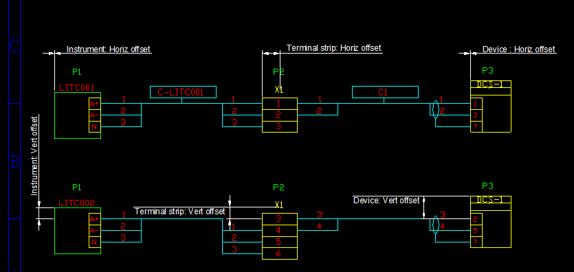
| Device: Horiz offset | Horizontal offset from the position of the component stage at which to insert the device symbol. |
| Device: Vert offset | Vertical offset from the position of the component stage at which to insert the device symbol. |
| Instrument: Horiz offset | Horizontal offset from the position of the component stage at which to insert the instrument symbol. |
| Instrument: Vert offset | Vertical offset from the position of the component stage at which to insert the instrument symbol. |
| Two-sided Instrument: Horiz offset | Horizontal offset from the position of the component stage at which to insert the two-sided instrument symbol. |
| Two-sided Instrument: Vert offset | Vertical offset from the position of the component stage at which to insert the two-sided instrument symbol. |
| Terminal strip: Horiz offset | Horizontal offset from the position of the component stage at which to insert the terminal strip symbol. |
| Terminal strip: Vert offset | Vertical offset from the position of the component stage at which to insert the terminal strip symbol. |
| PLC: Horiz offset | Horizontal offset from the position of the component stage at which to insert the PLC symbol. |
| PLC: Vert offset | Vertical offset from the position of the component stage at which to insert the PLC symbol. |
| I/O Channel: Horiz offset | Horizontal offset from the position of the component stage at which to insert the I/O Channel (A terminal group in a PLC) symbol. |
| I/O Channel: Vert offset | Vertical offset from the position of the component stage at which to insert the I/O Channel (A terminal group in a PLC) symbol. |
| Loop Generation Setting: | Description: |
|---|---|
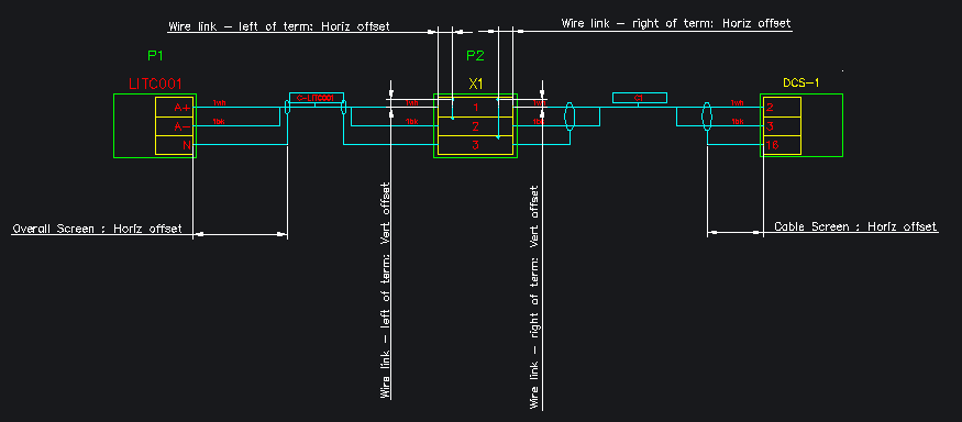
| Cable Screen : Horiz offset | Minimum Horizontal offset from the position of the terminal connection point at which to insert the Pair/triad screen symbol. |
| Overall Screen : Horiz offset | Minimum Horizontal offset from the position of the terminal connection point at which to insert the Overall screen symbol. |
| Wire link - left of term: Horiz offset | Horizontal offset from the position of the terminal at which to insert the input wire link. |
| Wire link - left of term: Vert offset | Vertical offset from the position of the terminal at which to insert the input wire link. |
| Wire link - right of term: Horiz offset | Horizontal offset from the end position of the terminal at which to insert the output wire link. |
| Wire link - right of term: Vert offset | Vertical offset from the end position of the terminal at which to insert the output wire link. |