How to Draw a Database Table on a Drawing
Fundamentals
The database import function is provided for the purpose of importing any dbase 3, 3+ or 4 database file onto a drawing. You may specify the tabular format (text size, column spacing, borders required etc.) and which fields and records you wish to import. This function will ensure that the text representing the database is aligned correctly during importation.
It is possible to import a single DBF file multiple times to different areas of the same DWG file. In this way you could, for example, place a bill of materials for devices on one side of your DWG layout and the bill of materials for terminals on the other side.
Column header blocks are inserted for each imported column. The column header blocks contain the configuration for the imported database table, which enables the database table data to be refreshed. The blocks are placed on the current layer but their attributes are on a hidden layer: tableconf. When the table data is refreshed, the text and border lines are erased and redrawn.
The lines and text for a column are always drawn on the same layer as the Column header block for that column. If you want to move an imported database or individual column of an imported database to a different layer, set the desired layer for the column header blocks and refresh the diagram.
The default column header block has a single visible POINT entity that appears on the current layer when the block is inserted. This means a window or crossing selection around at least the top of the inserted database will include selecting the column header blocks.
Considerable customisation of the appearance of the imported tables can be done by modifying the configuration information stored within the column header ("IMPCOL") blocks.
Procedures
Insertion
-
Select from the or Paneldes > Utilities and BOM menu.
Or, enter TEXTIMP on the CAD command line
Or, click the Import Database button on the ribbon/toolbar:

-
You will then be prompted to choose a file. You can choose either a DBF file (*.dbf), or an import configuration file (*.dbfimport.json) that you have previously saved:
- If you choose a .dbf report file, you will then need to organise and layout the table in the subsequent dialog, such as choosing which columns to include and how wide they should be.
- If you choose a .dbfimport.json configuration file, the table configuration stored in that file will automatically be loaded into the subsequent dialog, so that you can immediately insert the table if no further modifications are required.
-
The Import DBF File table configuration dialog will be displayed:
- If you chose a .dbf report file, you will be prompted to choose some columns to include.
- If you chose a .dbfimport.json configuration file, you should see the configured columns list already loaded.
-
Use the table configuration dialog to further configure the table.
-
When you have configured the table appropriately, click to insert the table.
If an insert point was specified, the table will be inserted at that location, otherwise, you must then select the insert location in CAD.
Note: The insert point will be the top left of the table data, ie, column data will be below (and to the right) of the insert point. Column headers (if any) will be placed above (and to the right) of the insert point.
-
Column header blocks containing the configuration will be inserted, and the table will be drawn.
If the output is not as desired (for example, a column is the incorrect width), you can easily edit the table, without having reconfigure everything from defaults.
-
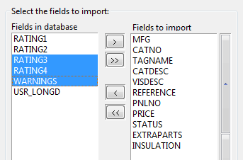
Select the fields that you wish to import from the database file.
The list titled Fields in database shows all of the fields or columns from the selected database.
The list titled Fields to import shows the fields that you have selected to import.
Use the [>>] or [<<] buttons to add or remove all fields from the list of fields to import.
Use the [>] or [<] buttons to add or remove only selected fields from the list of fields to import.
Use the buttons to the right of the Fields to import list to re-order the imported fields.
-
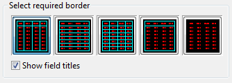
The five border options are displayed graphically in an array of buttons. Click the button for the border you require.
-
If you do not want the name of each database field displayed at the top of each column on the drawing, clear the Show field titles checkbox.
-
Enter the spacing data and the first and last records to import.
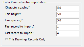
Character spacing? This value is an estimate of the average character width. If you find that your data overruns the width of the columns increase this value. To minimise the space the imported data uses horizontally, decrease this value. Text height? Enter the height of the text that you wish to use. If you modify this you may need to modify the previous spacing value. Line spacing? Enter the size of the gap to leave between lines of data. Any horizontal border lines constructed are placed in the centre this gap. First record to import? Enter the first record to place on the drawing. Defaults to 1, the first record in the database. Last record to import? Enter the last record to place on the drawing. Defaults to the last record in the database. -
You can choose to filter the data to include only the records that relate to the components found on the current drawing. To filter the data, tick the box "This drawings records only".
-
Click the [OK] button.
-
Pick the insertion point for the imported database. This will be the upper left corner of the table.
-
The function will insert a column header symbol for each column that you have selected to be imported.
-
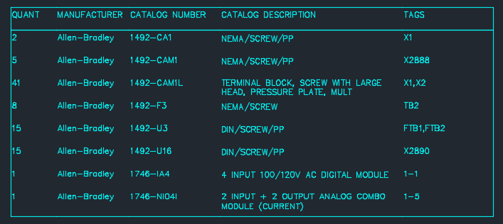
The database file will be imported as a table.
All construction uses CAD text entities, in the current style, and CAD line segments. The construction may be modified by any standard editing commands provided by your CAD package.
If you have used that database previously, your previously used settings for that database will be loaded into the interface.
Modification
Elecdes and Panldes allow you to modify and reconstruct an existing inserted table with the table configuration dialog interface.
-
Select from the or Paneldes > Utilities and BOM menu.
Or, enter TEXTIMPEDIT (or TIE) on the CAD command line
-
If there are multiple tables on the current drawing, select the table to edit from the list that is shown.
-
Use the table configuration dialog to modify the table.
-
Click to reinsert the modified table (the existing column header blocks will be deleted and recreated with the new configuration).
If you Cancel, the original table will not be modified.
Refresh
This function will refresh all of the imported database tables on the current drawing. The function operates without user interaction.
-
Select from the or Paneldes > Utilities and BOM menu.
-
The function will find and remove all text and lines that show the previous imported database data.
New text and lines will be inserted to show the current contents of any imported database tables.
You can refresh all of the imported database tables on all of the drawings in the current project from Ebase. See How to Update Databases Previously Imported in the Project (Ebase).
Table Configuration Dialog
The Table Configuration dialog used for creating or editing an imported DBF table.
Click on parts of the dialog image below for more details:
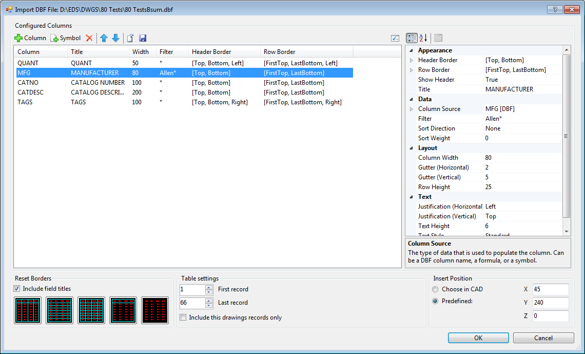
Configured Columns List
The configured columns list shows the columns that will be used to construct the table (including some of the more common properties), and allows addition, removal, and reordering.
When one or more columns in the list are selected, their full set of properties will be loaded into the property pane, on the right of the dialog, for editing.
Configured columns can also be loaded from and saved to configuration files on disk, allowing preconfigured tables to be shared between users, and reused between projects.
Adding Columns
Add DBF columns: Displays a list of columns from the DBF, then adds any chosen columns to the column list.
Add Symbol column: Opens a file browse dialog showing the EDS RFIN folder. When a DWG file is chosen, it will be added to the column list as a symbol column.
The properties of any added columns will be set to the default column property values.
Removing Columns
Columns can be removed from the configuration by selecting them, and clicking Remove on the toolbar.
Reordering Columns
Columns can be reordered by dragging and dropping, or by using the Move Up/Move Down buttons on the toolbar.
Multiple columns can be reordered at once by selecting more than one in the list.
Default Properties for New Columns
When a new column is added to the column list, its initial properties are copied from a default set of properties (stored in the el32.ini file).
The values of these default properties can be edited by clicking Edit default properties for new columns on the toolbar, which will show a dialog containing a column properties page, which functions in an identical manner to the properties page on the main dialog.
Column Properties
The column properties pane (on the right of the dialog) shows all the properties of the columns that are selected in the column list, and allows you to edit them.
When multiple columns are selected, mixed value properties will display as blank, and any changes made will be applied to all selected columns.
Properties that have had their values changed will be shown with bold text.
Below is a summary of column properties. These properties are converted to attributes in the column header blocks when the table is inserted.
| Section | Property | Details |
|---|---|---|
| Appearance | Header Border | Configures which border lines to show for the header of the column. You may also specify a symbol file name to insert a symbol for the header. The symbol is expected to be found in the RFIN directory of your EDS installation. |
| Row Border | Configures which border lines to show for each row in the column. | |
| Show Header | Specifies whether a header will be created for the column. | |
| Title | Text to show in the column header (eg the name of the column), if headers are shown. For new columns, this defaults to the column source name. | |
| Data | Column Source |
|
| Filter | Omits any records from the table where the value for this column does not match this filter. Supports equality, comparison, and wildcard operators. See Specmatch for details on defining a valid filter. | |
| Sort Direction | Specifies if or how the values in the column are used to sort the records in the table. | |
| Sort Weight | Determines the priority of this column when sorting the table, compared to other columns. The lowest weight shall be the primary sort column, the second lowest the secondary sort column, etc. | |
| Layout | Column Width | Width of the column, in drawing units. |
| Gutter (Horizontal) | Spacing between the text and the left and right edges of the column, in drawing units. | |
| Gutter (Vertical) | Spacing between the text and the top and bottom edges of the row, in drawing units. | |
| Row Height | Height of each row, in drawing units. For good results, ensure this value is greater than or equal to Text Height + 2x Gutter (Vertical) | |
| Text | Justification (Horz.) | Horizontal justification of the column text in the cell. |
| Justification (Vert.) | Vertical justification of the column text in the cell. | |
| Text Height | Height of the inserted text, in drawing units. When set to 0, the column will not be drawn, however it will continue being evaluated for filters/sorting. | |
| Text Style | The AutoCAD text style for the inserted text. If blank, will default to the current text style upon insertion of the table. |
Reset Borders
These buttons allow you to quickly (re)set column borders to commonly used styles, without having to use the column properties pane to adjust each column.
If Include field titles is ticked prior to selecting a border style, then the applied style will include a header row, otherwise, the header row will be turned off.
Note: The buttons only reset the border style when they are clicked - you can further modify borders in the column properties pane at any time.
Table Settings
These settings apply to the table as a whole.
First Record/Last Record: These allow you to include only a subset of records from the DBF file.
If the First Record is 1, and the Last Record is equal to the number of records, then all records will be included, and if the source DBF subsequently gets larger or smaller, then the number of rows in the inserted table will grow or shrink accordingly when refreshed on the drawing.
This drawings records only: the records of the DBF to be imported will only be included if TAG information (PNLNO, TAGNAME, TSTRIP etc) in that record matches TAG information used inside Elecdes blocks on the drawing the database is being imported into.
Insert Position
Specifies where on the drawing the table should be inserted.
- Choose in CAD: You will pick the table's insert point on the drawing when the dialog closes.
- Predefined: The table will be inserted at the point specified by the X, Y, and Z coordinates (in drawing units).
Note: The insert point will be the top left of the table data, ie, column data will be below (and to the right) of the insert point. Column headers (if any) will be placed above (and to the right) of the insert point.
Configuration files
Configuring tables can be a repetitive process, and also tedious if a prescribed set of drawing standards must be followed. To reduce the overhead of configuring tables, it is possible to save table configurations to a file on disk, and load configuration files back at a later time. In this way, you could create (for example), a configuration for a Bill of Materials table, then any user could load this for any drawing in any project, and get a table created that looks consistent, with no (or minimal) extra configuration required.
DBF Import configuration files have the extension .dbfimport.json, and are a text configuration file containing all of the settings and column properties that are editable on the dialog.
Configuration files store the name of the DBF from which they will import data. A relative path is prepended to the file name. If the DBF was an EDS report, then a placeholder for the project name is used, allowing reuse of a configuration between multiple projects.
Loading a Configuration
Click Load Configuration on the toolbar, then choose a configuration file (*.dbfimport.json) to load. Ensure you save any previous configuration before loading, if you wish to re-use it.
If the DBF file referenced in the configuration file cannot be found, you will be requested to select another DBF to use with the configuration.
Saving a Configuration
To save the current table configuration, click Save Configuration on the toolbar, then specify a recognisable file name and location.
Modifying the appearance of the imported data
It is not possible to simply stretch the columns to move or re-size them.
The text and lines for each column are inserted from the insertion point of the column header for that column. The width to redraw a column is stored in an attribute of the column header block for that column.
To move or re-size a column, you must thaw the tableconf layer, then move or edit the column header blocks.
The attributes of the column header blocks control most aspects of the databases representation within the drawing. By directly editing the column header blocks, you can also change the following:
Text style
Text justification
Column title
Column visibility
Sorting of rows
Filtering of rows
See Also
For details about the column header blocks, see Attributes of Symbols.