How to Create a Device with a Custom Terminal Layout
Multi-Terminal Device Fundamentals
Multi-Terminal Devices (MTDs) are User Created composite symbols. An MTD symbol is a nested block, which is exploded after insertion. Elecdes associates all of the individual parts of an MTD with a single device name. This is done via the TBLOCK attribute of MTD terminals and the TAGNAME attribute of the MTD Tag.
MTD symbols contain:
-
A number of specially named Elecdes terminal symbols.
-
An MTD tag symbol
-
Various graphical elements such as lines arcs and circles.
Specially named discrete terminal symbols are used to represent the device terminals. These terminal symbols are named HTTERMP and VTTERMP. Each terminal is treated as a discrete terminal during an interconnection analysis. These terminals do not appear in a bill of materials report.
The MTD tag symbol is used for bill of materials reporting. It contains catalog and naming information. It contains no useful graphical information.
The graphical parts (lines, arcs and circles) of the MTD symbol are grouped into a single block when the MTD symbol is saved. When inserted onto a drawing, they are not recognised by the interconnection analysis.
Other standard Elecdes symbols (devices etc.) may NOT be used within an MTD. You can cut and paste the graphical part of any symbol to an MTD but you must not include the attributes.
An MTD symbol can have any layout that you choose.
Note that the exploded elements of an MTD that is inserted into a drawing (tag symbol, terminal symbols and graphic block) are grouped after it is exploded, so it is selected like a single block. Use Ctrl-Shift-A to turn group selection ON/OFF.
Wiring Diagram Template Fundamentals
The MTD creator is also used to create templates for wiring diagrams. Wiring diagram templates are used to dictate the exact layout of the wiring diagram for a device. A wiring diagram template is a nested block, which is exploded after insertion. They have the same structure as MTD symbols.
Wiring diagram templates contain:
-
A number of specially named wiring diagram terminal symbols.
-
A wiring diagram tag symbol
-
Various "graphical" elements such as lines arcs and circles.
The "graphical" elements are grouped into a single block when the template is saved, in an identical manner to saving an MTD symbol.
For more information about using a template for a wiring diagram, see How to Use a Template to Layout a Wiring Diagram.
Creation / Editing Considerations
The icon MTD menus of symbols contain both MTD components and wiring diagram template components. You should only insert the appropriate components for the type of drawing you are creating. For example, when you are creating a wiring diagram template you should insert wiring diagram tag and terminal symbols. The different types of symbols can be identified by the information on the slides.
When inserting symbols or lines etc. onto an MTD you may need to switch layers. When inserted and exploded the individual parts of the symbol will remain on the layers on which they were placed when the symbol was created. Ensure that you select appropriate layers when constructing different parts of the symbol i.e. conductor lines, graphical information and terminals.
Do NOT copy an MTD symbol in the file system of your computer. The name of the graphical parts block within the symbol is expected to be related to the name of the symbol. Copying an MTD symbol file breaks this relationship. The MTD Name function, detailed below, enables copies of MTD symbols to be made correctly.
Procedure to Create or Edit an MTD symbol:
-
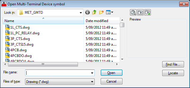
Select Create/Edit Multi-Terminal Devices from the Elecdes Main Menu.
-
You will be provided with a list of existing MTD's from the MTD directory.
Select one of the symbols for editing OR enter a new name for a new MTD symbol.
-
The chosen drawing will be opened.
If you have chosen an existing MTD symbol, the graphical parts block will be exploded after opening the symbol.
If you have created a new MTD symbol, it will be a copy of the MTD base drawing, gmtdbase.dwg, which can be found in the <EDS>\Elecdes\MSUPPORT or \ISUPPORT directory.
-
Use the MTD toolbar items, detailed beneath this procedure, to create or edit the contents of the symbol.
-
When you have completed editing the MTD symbol, save the file with the SAVE command of the CAD package. Elecdes will intercept this command. Elecdes must perform several operations on the MTD before saving it to a file.
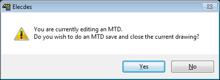
-
If you have not yet placed an MTD TAG on the symbol, you will be requested to do so.
You must place a TAG symbol on the new symbol to hold the device attributes for reporting.
Every MTD symbol must have one MTD tag symbol to hold the standard set of device attributes for reporting. Click OK, then insert a tag symbol onto your MTD (see below).
-
A graphical elements block will be created. This block will not be exploded when the symbol is inserted. The block will NOT affect the interconnection analysis. The block name will be based on the new symbol name. Each MTD symbol will have its own unique graphical elements block. All of the entities on the drawing, except the MTD TAG and the terminals, will automatically be "nested" inside the graphical parts block.
-
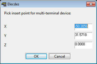
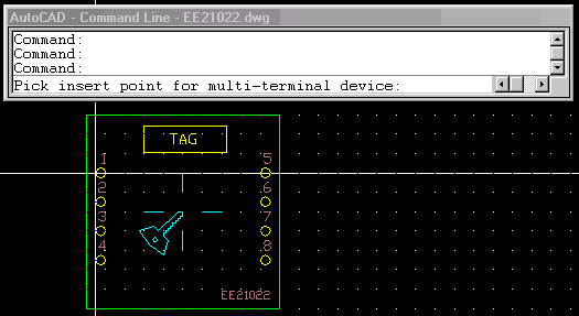
You will be asked for the insertion base point for the whole MTD symbol.
-
The symbol will be saved in the MTD directory.
-
You may select this symbol for insertion into a schematic drawing by selecting the menu item from the menu.
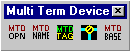
Multi-Terminal Device Creation toolbar
 MTD Open
This toolbar button performs the same function as selecting Create/Edit Multi-Terminal Devices from the Elecdes Main Menu. It can be used to begin editing or creating an MTD symbol.
 MTD Name
This function will create a copy of the currently open MTD symbol with a new name.
Do NOT copy an MTD symbol in the file system of your computer. The name of the graphical parts block within the symbol is expected to be related to the name of the symbol. Copying an MTD symbol breaks this relationship.
-
Open the MTD symbol to be copied in an MTD editing session.
-
Click the MTD Name toolbar button.
-
Enter a new name for the MTD symbol in the file-save dialog box.
-
The current drawing will now be converted to, recognised and saved as the new MTD name.
 MTD Tag
This item will display an icon menu of MTD tag symbols and wiring diagram tag symbols.
MTD Tag blocks
The MTD tag symbols are: himtdt.dwg or vimtdt.dwg. These symbols have no important graphical information. They contain the standard attributes of an Elecdes device symbol. Every MTD MUST have one TAG symbol inserted to hold this information. You will not be able to save the MTD until you insert a TAG symbol.
This symbol is used to hold the attribute data required for reporting the MTD symbol in the Bill of Materials. When you place it on the MTD, no attributes will be requested. Attributes, including TAGNAME, are requested when the MTD symbol is inserted onto a schematic drawing.
The TAGNAME attribute will be set, during MTD creation, to the text "TAG". The terminal attributes (T1...T6) of the TAG symbol are unused.
You may create alternative tag symbols with differing graphical appearance as required. The samples provided have a tag with a surrounding box and one with no graphical elements.
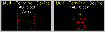
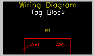
Wiring diagram Tag block
The wiring diagram tag symbol is: wdTag.dwg. Every wiring diagram template must have one TAG symbol. You will not be able to save the template until you insert a TAG symbol.
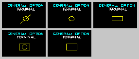
 Terminal
This item will display an icon menu of MTD terminal symbols and wiring diagram terminal symbols.
MTD terminal symbols
The MTD terminal symbols are: httermp.dwg or vttermp.dwg. The name of these symbols identifies them as terminals of an MTD. These terminals will not be reported in the Bill of Materials report but, you can cross-reference the MTD terminals. For all other operations, such as interconnection analysis, these terminals are identical to the Elecdes standard discrete terminal symbols.
When inserting MTD terminals, the terminal number (T1 attribute) is the only attribute requested. The TBLOCK attribute will be loaded with the MTD TAGNAME when the MTD is inserted into a drawing.
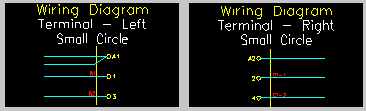
Wiring diagram Terminal symbols
The wiring diagram terminal symbols are: wdLt.dwg or wdRt.dwg. The terminals are specific to either the left or right side of the wiring diagram. When placed vertically the terminals are read from the right side of the drawing. A terminal on the bottom of the diagram will be a rotated left side terminal and a terminal on the top of the diagram will be a rotated right side terminal.
When inserting wiring diagram terminals, the terminal number (TERM attribute) is the only attribute requested.
 MTD Base
This function allows you to pick the insertion base point for the symbol graphically. This is the point by which the symbol will be located when it is inserted into a schematic drawing.
When an MTD is inserted, existing lines on the drawing will be broken by a box that surrounds the terminals of the MTD. Generally you should ensure the base point of the MTD is aligned with the topmost leftmost terminal.
The function is setting the drawing variable INSBASE in the CAD package.
When the MTD symbol is saved, the current insertion base point is confirmed in a dialog.
Base point for wiring diagram templates
The base point for a wiring diagram template will define the point by which the symbol is located when it is inserted into a wiring diagram. Generally you should ensure that the base point is aligned with the top-left corner of the template.