How to Draw a Transformer Link to a 3 Phase Bus
Fundamentals
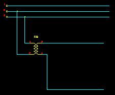
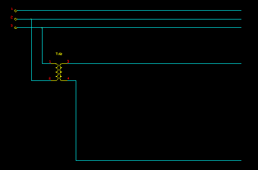
This function constructs a connection to a 3-phase power circuit, inserts a control supply transformer and allows you to extend ladder rails, from the transformer, for your control circuits.
Example:
Procedure
-
Select Construct TXformer link to 3Phase from the Elecdes > Drawing Macros menu.
-
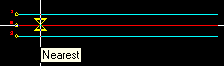
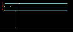
You will then be asked to pick the first 3-phase supply connection.
You should place this point on a 3-phase bus, on one of the lines you wish to use for supplying your transformer.
The orientation of this line is assumed to be the orientation of the ladder rails you wish to produce. If you do not select a LINE for this point you will be required to enter the orientation of the ladder rails you wish to produce.
-
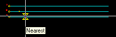
Next you must select the second 3-phase supply connection.
You should place this point on a 3-phase bus, on the second of the lines you wish to use for supplying your transformer.
-
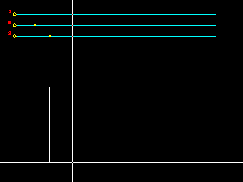
You must then specify the distance between the bus and the ladder that you wish to create.
This distance must be specified by picking a point at the distance required.
-
You must then specify the distance between rails of the ladder that you wish to create.
This distance must be specified by picking a point at the distance required.
-
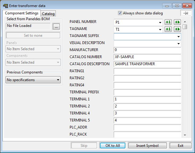
The Elecdes Component Dialog will be displayed allowing you to enter and select attribute data for the transformer. Refer to the section How to Insert Symbols for more information on entering and selecting attribute data for the transformer.
-
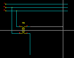
Finally, you must select the length of the rails that will extend from the transformer.
This distance must be specified by picking a point at the distance required.
-
The construction will finish.