Electrical Design Software | Elecdes Design Suite by Scada Systems Ltd

How to Route and View Wires and Cables

General

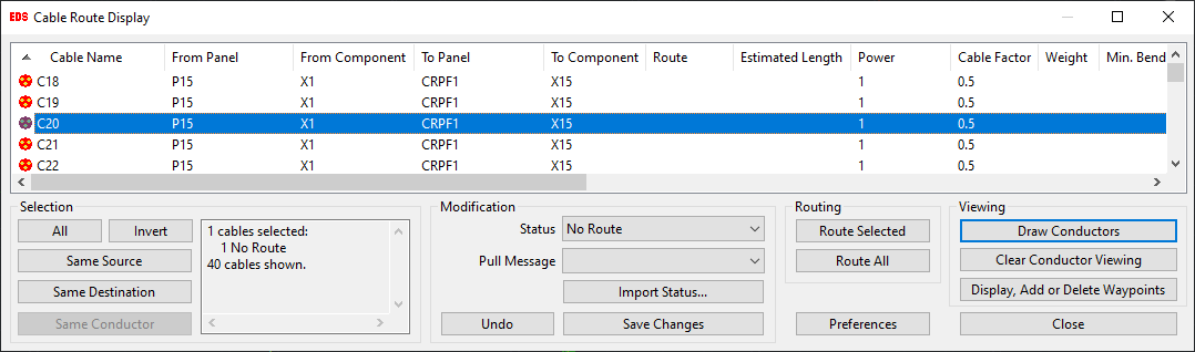
The Cable Route Display dialog is allows you to route, view, select waypoints, and modify your conductors (cables / wires). Cable or wire routing runs the route optimisation process and provides you with diagnostic information for tuning your model.

The viewing functions allow you to visualise the routes that have been calculated by Paneldes.

The options for cable routing differ slightly from the options for wire routing.

Procedure for Cable routing

  1. Click the Route and View Cables button in the Cable Manager dialog. Cable Manager can be accessed from the Routing: Wire and Cable menu.

    You will be presented with the Cable Route Display dialog as shown below.

  2. Click the Preferences button to set appropriate routing settings for your model in Paneldes preferences.

  3. You can use the selection buttons along the top of the dialog to select a group of cables for routing.

  4. Once your cables are selected you can route them by clicking on Route Selected. Alternatively, click Route All to route all of the cables regardless of which are selected. This will run the Route Optimisation Process for each cable and updates or creates various DBF format report files.

  5. Paneldes will present you the Route Optimisation summary. Press OK if you are satisfied with the Routing Summary, otherwise you can tune your model and run cable routing again.

  6. Once routing is finished successfully, you will notice that the Route Column is updated with a cable route name for each cable that was routed successfully e.g. C20_ROUTE as shown below.

  7. You will need to check that your cables are in the appropriate trays, conduits etc. and that the routes found by Paneldes are suitable.

    You can check your cables by drawing and viewing them by clicking on Draw Conductors button on cables selected in the list. Terminating devices or panels will be drawn even if there is no route found for the cable.

  8. You can remove/clear all the conductors drawn on your model by clicking on Clear Conductor Viewing button.

  9. You can query the waypoint segments of a selected cable and choose to modify the waypoints by clicking Display, Add or Delete Waypoints.

  10. You apply various modifications to your cables e.g. changing cable status, setting a pull message etc. click here to find How to modify your cable(s) status.

  11. Pressing the button Undo will undo the recent change(s) made to your cables. Every time you press the Undo button it will step back to the previous change you made to the cable list.

  12. Pressing the button Save will save all the modifications that you have made to your cables list using the cable route display dialog. Paneldes will ask you to save any unsaved changes before exiting the cable route display dialog as shown in the image below.

Procedure for Wire routing

  1. Click the Route and View Wires button in the Cable Manager dialog. Cable Manager can be accessed from the Routing: Wire and Cable menu.

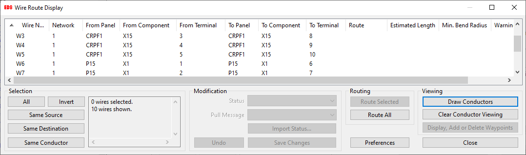
    You will be presented with the Wire Route Display dialog as shown below.

  2. Click the Preferences button to set appropriate routing settings for your model in Paneldes preferences.

  3. You can route your wires by clicking on Route All.

  4. Paneldes will present the Route Optimisation summary. Press OK if you are satisfied with the Routing Summary, otherwise you can tune your model and run wire routing again.

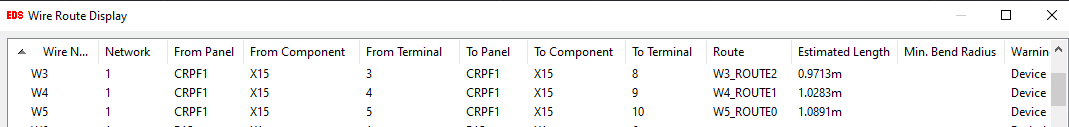
  5. Once routing is finished successfully, you will notice that the Route Column is updated with a wire route name for each wire that was routed successfully e.g. W3_ROUTE2 as shown below.

  6. You will need to check that the wire routes found by Paneldes are suitable. You can check your wires by drawing and viewing them by clicking on Draw Conductors button.

  7. You can remove/clear all the conductors drawn on your model by clicking on Clear Conductor Viewing button.

Notes:

  • It is very important to note that when you modify the status of a cable to ISSUED or PULLED, it may impact the routes of other cables ( i.e. the cables which are using the same route but not ISSUED or PULLED yet ).

    Therefore, to avoid any inconsistencies with cables that are not ISSUED or PULLED, you must run the routing again on all of the cables once a cable is ISSUED or PULLED.

  • You must run the routing functions before using the viewing functions re. the routing process.

  • During viewing, many of the Paneldes layers are automatically turned "off" for visual clarity. Use the Clear Routes button inside Cable Manager to return to a normal model view.

  • During viewing, cable and wire routes are drawn on the Paneldes "routedisp" layer.

  • During viewing, the "Construction" layers for raceway envelope are left visible so you can view the raceway that the conductor is routed through.

  • Labels are attached to the lines of the viewed route to identify the conductor.

  • The line for the conductor route is drawn with a non-zero lineweight to enhance visibility.

  • If cables are drawn as solids, the diameter of the cable is obtained from the first of the cable catalog columns: OD, DIAM, DIAMETER, OD_DIAM or ODIAMETER that contains a value.

  • You can query a conductor after you have used this tool to view its route.

  • Raceway segments from locked routes that are missing from the model will be skipped when viewing the route. The straight line across the gap vacated by the missing segment will be used in its place.

See also

How to Configure the General Settings

How to Configure the General Routing Settings

How to Configure Cable Routing Settings

How to Configure Wire Routing Settings

Route optimisation errors and warnings

How to route wires on multiple panel models.

How to route cables from a single project on multiple workstations

How to use the NEC code to calculate raceway fill for trays and conduits.

How to Draw a Route Segment Cross Section Table.

How to Tune Your Model for Wire and Cable Routing.

How to Optimise the Termination Order for Wires.

Route List Diagnostic data ( RLIST.TXT )

Segment to Panel Connection data (SegToPanelConnections.txt)

How to View Wire and Cable Routes and lock, unlock, pull and issue cables

General

After running route optimisation you will need to check that your cables and wires are in the appropriate trays, ducts etc. and that the optimal routes, which Paneldes has assigned, are the routes that you had planned for your conductors.

Paneldes provides a diagnostic tool for you to view each cable / wire, in its route, for the purpose of checking your route optimisation results. The viewing functions allow you to visualise the routes that have been calculated by Paneldes.

If you need further information about the routing process that has occured, to assist in diagnosing issues that you have observed, Paneldes optionally provides the diagnostic output data files: RLIST.TXT and SegToPanelConnections.txt. These files can tell you how Paneldes connected trays together for routing and other details. The files are described below.

Notes:

  • You must run the routing functions before using the viewing functions re. the routing process.

  • During viewing, many of the Paneldes layers are automatically turned "off" for visual clarity. Use the Clear Routes button inside Cable Manager to return to a normal model view.

  • During viewing, cable and wire routes are drawn on the Paneldes "routedisp" layer.

  • During viewing, the "Construction" layers for raceway envelope are left visible so you can view the raceway that the conductor is routed through.

  • Labels are attached to the lines of the viewed route to identify the conductor.

  • The line for the conductor route is drawn with a non-zero lineweight to enhance visibility.

  • You can query a conductor after you have used this tool to view its route.

  • Raceway segments from locked routes that are missing from the model will be skipped when viewing the route. The straight line across the gap vacated by the missing segment will be used in its place.

Procedure

  1. Click Wire Routes or Cable Routes in the Cable Manager dialog. The Cable Manager can be accessed from the Routing: Wire and Cable menu.

    If you have not modified your model, you can load cached data to reduce the time required to load the route segment connections and panel and device lists.

    • For wire viewing function, a list of wire and their routes is displayed, as shown in the following dialog:

    • For cable viewing function, a list of cables and their routes is displayed, as shown in the following dialog:

    • The conductor list can be sorted by any column of data displayed in the list. This is done by clicking on the headings of the columns. The order of the columns can also be rearranged to allow easy sorting and identification of conductors of interest. This is done by dragging the column headings.

    • Select the routes you wish to view by clicking on the entries in the list.

    • You can use the selection buttons along the top of the dialog to select groups of routes.

    • Once you have selected the routes you wish to draw, click Draw to view them. The conductor will be drawn on the drawing. If you are using the cable route diagram, terminating devices or panels will be drawn even if there is no route found for the cable.

    • You can display the guidance for the wire by clicking Display guidance on the wire route dialog.

    • You can change the status of cable(s) using the Status combo-box on the cable route dialog.

    • You can query the waypoint segments of the selected cables by clicking Display Waypoints and Panels on the cable route dialog.

    • To remove the drawn routes click Clear Routes in Cable Manager.

RLIST.TXT Diagnostic Data

If you need further information about the routing process that has occured, to assist in diagnosing issues that you have observed, Paneldes optionally provides a diagnostic output data file. The file is RLIST.TXT. This can tell you how Paneldes has connected trays together for routing and also provides other connection details. This file will often be used to explain why a cable seems to route in a path that was not expected, for example, 2 trays that appear to join however did not form a junction.

The first part of the file describes the raceway connection preferences, specifically the preferences that influence the connection behavior of the raceway.

Each following section of the file describes one raceway segment (tray, conduit or similar) and its connections. All segments are included in the file.

A section of this file would appear as follows:

Seg 1344 of 5585: GZ899-4808#2
CLASS: CABTRAY PWR [ 400,230 ] CF [ 848.00 ] WF [ 3.00 ] Length [ 0.3740m ]
Major end positions: ( 69448.1508,218174.7532,-500.0000 ) - ( 69448.1508,218548.7533,-500.0000 )
Raceway network: 1
RouteConnections:
Seg 1343 - GZ899-4808#1 Snug tray 0 at end 0. PWR [ 400,230 ] CF [ 848.00 ] WF [ 3.00 ]
Seg 1345 - GZ899-4820#1 Connection 1 at end 0. PWR [ 400,230 ] CF [ 848.00 ] WF [ 3.00 ]
Seg 4698 - UG496C.1 Connection 2 at end 0. PWR [ 400,230 ] CF [ 1200.00 ] WF [ 5.00 ]
Seg 1250 - GZ599-4811 Snug tray 0 at end 1. PWR [ 400,230 ] CF [ 848.00 ] WF [ 3.00 ]

The first line in each section contains the segment number (e.g. 1344) and tagname (e.g GZ899-4808#2 ). The segment number is often used in other parts of this file when referencing back to connections from other raceway segments.

The second line describes the CLASS (type of raceway component) and the POWER level number for that segment of raceway. The length of the raceway is also included on this line. When POWER levels do not match the raceway segments will not join.

The third line describes the end points in 3D space of the raceway segment. With this data you can check to see if two segments are close enough to each other to form a connection. The network number is also displayed. Raceway on the same network is theoretically joined and should be, at least, indirectly connected.

The list of "RouteConnections" that follows the third line describes each raceway segment that connects to segment 1344. The other segments have some of their properties listed and the type of connection formed. This list will quickly establish if your two trays have formed a junction/connection.

All connections are listed including REAL connections, DUMMY connections and BRIDGING connections. Dummy connections are created when a route is LOCKED and segments that were saved in that route are somehow lost or deleted. Paneldes forms a new connection which jumps the missing segment. BRIDGING connections are formed when bottleneck passes allow separated networks to artificially bridge (connect) to find a route when no route was found (due to network disconnection).

SegToPanelConnections.txt Diagnostic Data

You can enable a logging option so that Paneldes will create a text file listing the names of the route segments that are considered to be connected to each device or panel for each wire or cable route.

Paneldes will create a text file with the name <project>SegToPanelConnections.txt.

A section of this file would appear as follows:

Cablename: 'C101'

    Pass: Initial, Main trace

    Power 0

    Cablefactor 1.00

    Weight 0.0560

    3 connections to panel/device 'CRPF1'.

        'TRAY102x' on network 47 at distance 0.8016m with power '0', cablefactor 40.00 and weight factor 1.2960.

        'TRAY001' on network 47 at distance 1.5307m with power '0', cablefactor 4.00 and weight factor 0.1800.

        'TRAY217#1' on network 1 at distance 1.5761m with power '4', cablefactor 4.0 and weight factor 0.1800.

    1 connections to panel/device 'FP1'.

        'TRAY103' on network 47 at distance 0.6486m with power '0', cablefactor 0.00 and weight factor 0.0000.

The first line specifies the name of the cable.

The second line specifies which routing pass the section applies to. There are at least two preliminary passes and one main pass for each route. There may be more passes if bottleneck passes are enabled.

The third to fifth lines specify the power, cable factor and weight of the cable.

The following lines list the route segment connections that are considered valid or useable to the device or panel at each end of the cable. For each segment the distance between the segment and the device or panel, the power value for the segment, the cable factor and the weight factor of the segment are listed.

See also

You can change the lineweight for viewed conductors, the spacing between the conductor labels and whether layers are turned off during route viewing. For more information see How to Configure the General Settings.