How to Draw a Route Segment Cross Section Table
General
Route segment cross section lists can be placed on the drawing in tabular form. The cross section list will show the segment tagname followed by a list of the cables or wires routed through that segment. The data shown is taken from selected fields of the cross section reports for wires and cables. These cross section reports are created when you generate wire and cable routes. They are created in the current Elecdes project directory.
Procedure
-
It is best to remove any raceway 3D construction before continuing as it makes it easier to pick route segments to list conductors for. See Deleting Raceway Construction.
-
Select the Import duct/cable X Sect entry from the Routing: Wire and Cable menu.
-
You will be displayed a dialog box asking whether you wish to display the route cross section data in model space or paper space. Paper space will normally give the best results.
-
Select Yes, for paper space, to display the cross section list in the same units as your border sheet (i.e. 1 drawing unit = 1 border sheet unit) and for text to be placed in the plane of the border sheet.
Select No, for model space, to display the cross section list in the same units as your model. (i.e. 1 drawing unit = 1 x the base drawing units of FT or M, you may enter units such as IN, FT, MM or M to scale the table size). Table text will be placed in the plane of the current model space UCS.
If you draw cross section tables in paper space and subsequently change the view of your model in one or more viewports, you may need to re-align the tables with the new view of your model.
-
The Text Size will now be requested.
If using model space, enter the table text size in scaled units (e.g. 20cm, 5in). If using paper space, enter the size in drawing units - relative to your border sheet scale (e.g. for metric 5.0 and for imperial 0.25).
-
You will then be asked if you wish to list wires or cables.
-
You will be asked to select the route segment for which you wish to list conductors. Select a single route segment from the model. If you are currently in paper space you will be automatically switched to model space before selecting the route segment.
-
If you have picked a conduit length that is in a Ductbank you will be asked if you want to draw the cross section for the whole Ductbank or only the individual conduit that you picked. A Ductbank is a group of conduit lengths that are close together and parallel to each other. Paneldes treats them as a single route segment to improve routing speed. When you draw a cross section for a Ductbank, Paneldes will draw an array of circles representing each conduit in the ductbank and will place the names of the conductors in each conduit next to the circle.
-
Next pick the insertion point for the upper left corner of the cross section table. If you have selected to draw the table in paper space you will automatically be switched to paper space before picking the insertion point. The table will be drawn with the route segment tag name at the top followed by the list of conductors routed through the selected segment. Border lines will be drawn around the list.
-
The cross section tables consist of standard AutoCAD lines and text. After they have been inserted they may be modified as you require.
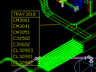
The following example shows cable tray segment TRAY3018 containing cables CM3061, CM3041, CM3051, C30502, C30602, CL30903, CL30901, CL30902. The cross section table was produced in paperspace. Note that the table is shown larger than normal for clarity.