Ductbanks
General
A ductbank is an array of conduits placed inside a trench. Paneldes provides a Ductbank Editor to quickly create ductbanks inside trench you have placed in your plant model. This section provides a description of the ductbank system and the ductbank editor.
Placing ductbanks
The procedure for placing ductbanks is outlined in How to place a ductbank, and How to edit an existing ductbank.
Ductbank editing interface
The ductbank dialog is used to define a cross section for each trench you have placed on your model. It can smartly continue an array of parallel conduits from one trench to the next, without much user intervention.
The user must ensure the cross section of conduits is complete and accurate for each trench then request that they be constructed or modified.
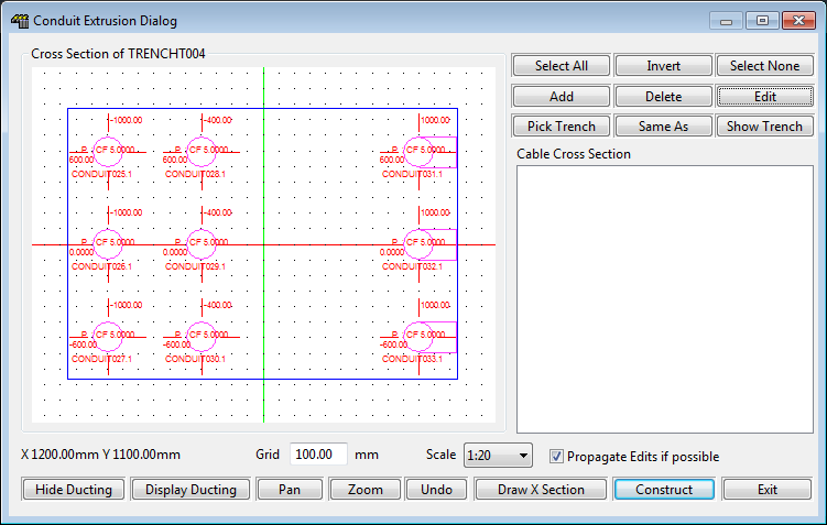
The user interface has a drawing area on the left and a cables list on the right, several "function" buttons on the lower edge of the dialog and several editing buttons on the right side.
Conduit Cross Section
The drawing area on the left shows you the current cross section including the conduits, their centre line positions, their sizes, their features (stub up, peel). You can PAN with the right mouse button and ZOOM with the "scale" control. The grid can also be modified.
-
Green coloured conduits have already been placed in the ductbank. You may edit their properties or delete them from the ductbank.
-
Pink coloured conduits are new conduits. Conduits that you add will be pink.
-
Pink conduits already placed in the cross section when you start the ductbank editor are suggested continuations from conduits in a connected trench segment.
To edit a conduit, select one or more conduits by clicking on them or dragging a box around them. To move a conduit, click and drag it within the conduit cross section window. Dragged conduits will snap to the current grid. Change the grid by entering a new value into the edit box.
Many of the editing operations you can perform MAY be propagated to the end of the ductbank you are editing, changing many conduits in a single operation. To achieve this you must ensure that you have the "Propagate changes" checkbox checked. The following operations will propagate where possible if enabled: Move, Size and spec. change and Delete.
Grid Size
The size of the grid that is displayed in the cross section of the conduits can be changed by entering a new value in the "Grid" box under the picture of the conduits.
Note that the grid is a proper value with units. Conduits will snap to the grid when you move them with the mouse.
Font Size
The size of the font that appears in the cross section of the conduits is set by the CONDEXT_FONTSIZE variable in the [Paneldes] section of the EL32.INI file.
Cable Cross Section
The cable list on the right is used to display any cables that are currently routed through the trench you are editing. Within the Cable Manager you can dictate that the conduits within a trench are not used for routing while constructing your ductbanks. This allows you to view the cables that will be likely to travel through the trench, in this list, while defining conduits.
See Preparation for Ductbank Editing in the section How to generate wire and cable routes.
Function Buttons (lower edge of the dialog)

|
Hide Ducting Display Ducting |
Turns the green 3D envelope on and off in the model. This may assist if things become cluttered. |
| Pan, Zoom and Undo | Basic AutoCAD commands that can be accessed from this dialog. |
| Draw X Section | Draws a 2D labelled cross section diagram of the conduits in the selected trench. |
| Construct | Accept the current conduit definitions and DRAW / RE-DRAW the conduits of the trench. |
| Exit | Quit from the dialog to the CAD session. |
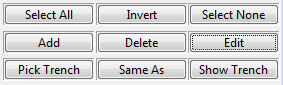
Conduit Editing Buttons (top right of the dialog)
|
Select All Invert Select None |
These are used to select one or more conduits for editing. You can also click on individual conduits or drag a window around them to change a selection. |
| Add | This button allows you to select and name a new conduit to include in your ductbank. After you have selected the type and named the conduit, you will be automatically placed in to a drag, to locate the conduit, in the cross section. |
| Delete | Deletes all selected conduits from the cross section. If you are editing conduits that have already been placed in the trench, then they will be marked with a black X in the Conduit Cross Section Window, and they will be removed from the trench when you click Construct. |
| [Shift] – Delete |
Pressing the SHIFT key on your keyboard and clicking Delete marks a conduit to be ignored. Ignored conduits will be marked with a red X in the Conduit Cross Section window. Ignored conduits are not re-constructed when you click Construct. |
| Edit | Allows you to edit the properties of the selected conduits. Clicking the right mouse button on a conduit also activates this button. More detail is given in the next section on changing the conduit properties. |
| Pick Trench |
Select a different trench to edit. This will return to the CAD window so that you may choose the correct trench. When you select a trench you must also select an END of the trench to "look in to". The end you select to "look into" will match the alignment of the conduit drawing area. |
| Same As | Allows you to clone the conduit layout of another trench. This will return to the CAD window so that you may choose the trench to clone. |
| Show Trench | Moves and zooms the CAD view to show the currently selected trench. |
Properties of conduits in the ductbanks
The conduits that you have selected to edit have many properties that you can change with the properties dialog box. You can activate the properties dialog box by selecting one or more conduits then pressing the EDIT button or right clicking your mouse over a conduit.
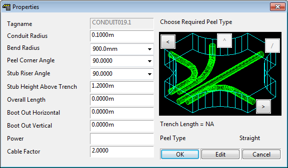
The properties dialog contains a list of dimensions and angles on the left, a cornering graphic on the right and some control buttons at the base.
Peel Type
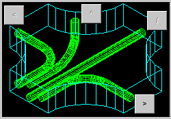
The cornering graphic contains buttons allowing you to select a "peel type" for any 3 or 4-way trench junction or select to "stub up" for any trench. It is not necessary for the user to select to corner or turn within corner trenches and riser trenches, this will occur automatically.
This cornering graphic defines the "feature of a conduit" displayed in the drawing area of the main ductbank dialog. The feature or "peel type" is also displayed on the left side of this dialog.
The Control buttons and Editable Dimensions
The dimensions on the conduit properties dialog relate directly to the requirements of ductbank editing. Other properties of a conduit, including its name and catalog specification, are accessed by clicking the Edit button.
Some dimensions may have non-zero values that are not used unless the conduit has the appropriate peel type. For example, the stub riser angle is not used if the conduit is peeled out to the right. However, it may have a non-zero value.
| OK, Cancel | Accept or reject changes to a conduit and then exit. |
| Edit | Reselect the conduit(s) specification from the catalog or re-enter its tagname. |
| Conduit Radius | The conduit radius (from the catalog specification). Units are required. |
| Bend Radius | The radius of the bend in the conduit if it is peeled out or a stub up. Units are required. |
|
Peel Corner Angle Stub Riser Angle |
The corner angles of the conduit bends, if the conduit is peeled or a stub up. |
| Stub Height Above Trench | Height above the top of the trench where a stub up will end. |
| Overall length. | Distance from "look in" end of the trench to the end of this conduit. The length is always in the direction of the trench route line, even if the conduit has a boot-out offset – see boot-out below. Units are required. |
|
Boot Out Horizontal Boot Out Vertical |
Specify the offset of the far end of the conduit in either or both of the horizontal and vertical direction. Used primarily when conduits are "booted out " of the side of a trench. Units are required. |
| Power | Specify the standard raceway property of power setting for the conduit. |
| Cable Factor | Specify the standard raceway property of cable factor for the conduit. |
Continuous Conduit Naming: Conduit Runs
Conduits will be named according to the name sequencer. The name sequencer will generate a conduit name when you Add a new conduit to a ductbank cross section during editing.
Once you accept the name, then the conduit will have a suffix appended before construction.
For example, when you click Add, the naming sequencer may offer you "CONDUIT100". If you accept this, then the conduit you add will be named "CONDUIT100.1".
When the ductbank system connects a new conduit to "CONDUIT100.1" at a later stage, only the suffix for the new conduit will change. Therefore a route is likely to be "CONDUIT100.1", "CONDUIT100.2", "CONDUIT100.3" etc. This is called a Conduit Run.
Conduit runs are summarised in the Issued and Pulled route lists.
You can change the delimiter that comes between the conduit name and its suffix. See Conduit run delimiter in How to Configure the Wire and Cable Routing Settings.
Construction of Conduits
The ductbank editor constructs conduits exactly as if you had created them individually with Paneldes.
To construct all conduits within the cross section of a trench at any time press the Construct button.
Corner angle too tight
If Paneldes finds a bend angle and radius which is too "tight" to fit in a ductbank's trench corner, it will not construct the bend with a curved conduit. It will approximate this bend with a straight section of conduit. This has negligible effect on any other operations including routing. This will occur during initial placement and also if a conduit is moved laterally in the editor, across the face of a trench toward the centre line of a trench bend.