Cross Reference Symbols and the Single Line Zone
General
Cross reference control symbols
The following symbols are used for cross-reference back annotation. They are stored with the Reference and Indicator symbols.
NOTE: The reference list or table title symbols (rhead ) have gained a PNLNO attribute since EDS 3.5x. When you cross-reference an older drawing, the old reference list title symbols will be replaced as required.
-
rheadh.dwg and rheadv.dwg
This is the reference list title block, placed automatically on an Elecdes drawing by the cross-referencing system. References for a duplicated Elecdes component will be listed underneath this title block. This title block may be moved at any time and NEWLY GENERATED references will be placed underneath.
-
rheadnh.dwg and rheadnv.dwg
This is the title block for a normally open / normally closed contact table ("NONC Table"), placed automatically on an Elecdes drawing by the cross-referencing system. References for the contacts of a relay will be listed underneath this title block. This title block may be moved at any time and NEWLY GENERATED references will be placed underneath.
The NO/NC contact table style of cross-reference is selected in the cross-reference preference page.
-
rheadh_b.dwg, rheadv_b.dwg, rheadh_t.dwg, and rheadv_t.dwg
These are special reference list title blocks, placed automatically on an Elecdes drawing by the Import BOM / Cross-reference tables system. References for a duplicated Elecdes component will be listed underneath these title blocks. These title blocks may be moved at any time and NEWLY GENERATED references will be placed underneath.
-
bhead.dwg
This is a header symbol specifically for a BOM / cross-reference table, placed automatically on an Elecdes drawing by the Import BOM / Cross-reference tables system. The BOM / cross-reference table is inserted underneath this header.
-
rheadt.dwg
This symbol has identical function to rheadh / v.dwg except it graphically represents the top row of a table AND will cause table type references to be placed underneath instead of the default list type. This block must be inserted manually when tabular references are required.
-
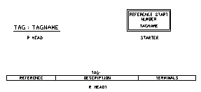
startref.dwg
This symbol should be placed on a drawing when a contiguous numbering system is used, for cross-referencing, (1 dimensional zoning). The symbol has a single attribute that should be loaded with the NUMBER corresponding to the first reference on the sheet. Elecdes will use this number to offset all references on the drawing sheet.
NB. This is not required if you are using Elecdes ZONE symbols to identify zones or rungs.
-
zone.dwg
This symbol is used to mark an arbitrary cross-referencing zone. All references to components within the boundaries of the zone use the tag of the zone as the reference text. The boundaries of the zone are also stored in the attributes of the zone symbol. The boundaries are not marked permanently on the drawing.
-
1Lzone.dwg
This symbol is used to mark an area of a drawing as a single line diagram. The Elecdes reporting and conductor analysis functions will not attempt to extract the same detail from the single line diagram as from a detailed schematic drawing. The boundaries of the 1Lzone are stored in the attributes of the zone symbol. The boundaries are not marked permanently on the drawing.
Cross reference list symbols
Reference List symbols are inserted automatically by the Elecdes Cross-Referencing function during cross-reference back annotation. These symbols are used to build:
-
reference lists beneath the reference list header symbol, described above.
-
reference tables beneath the reference table header symbol, described above.
Elecdes can provide textual, graphical or tabular cross-reference lists. The list will consist of the following:
-
A textual reference where no reference symbol is available.
-
A reference symbol, which is graphically similar to the original symbol that it references.
-
A table row symbol if the reference list is built beneath an RHEADT reference table header.
"Complete" reference symbols
The cross-references for a component can be shown using a single user-defined block that contains all of the cross-reference information and a user-defined graphic. Such a block is called a complete reference symbol and is essentially a template for a cross-reference contained in one block. This type of cross-reference replaces the standard reference header and table/list that are described above.
A complete reference symbol is actually a reference header (rhead*.dwg) but with extra attributes. See Cross Reference Symbol Attributes.
Further Information on Cross Referencing
A full discussion of Cross Referencing can be found in the Cross Reference section.
Refer to Ebase help for information on how to Back Annotate all of the drawings in the project with cross-referencing information.
Refer to How to Cross Reference Coils and Contacts for information on how to annotate the current drawing.
Further information regarding cross-referencing with zones can be found in the section Cross-reference a drawing with rung numbers (Zones).
Further information regarding marking single line diagrams can be found in the section How to Mark a Drawing as a Single Line Diagram.
Further information regarding inserting a combined materials / reference table can be found in the section How to Import a Materials / Reference Table on to a Drawing.
File names of cross reference control symbols
rheadh.dwg and rheadv.dwg – Header block for a standard cross-reference list.
rheadnh.dwg and rheadnv.dwg – Header block for a normally open / normally closed contact table.
rheadh_b.dwg, rheadv_b.dwg, rheadh_t.dwg, rheadv_t.dwg and bhead.dwg – Header blocks for a BOM / reference table.
rheadt.dwg - Header block for a tabular cross-reference list.
startref.dwg - cross-reference contiguous numbering / alternate name data block.
Unlike component symbols, the orientation character, 'h' or 'v' is placed at the end of the file name, if it is required.
Elecdes Symbol Naming Conventions
File names of cross reference list symbols
The file/block names for all reference symbols begin with a prefix of 'hx' or 'vx'.
The reference symbols are named in the following manner:
For a device block e.g. vi / hi3pcos.dwg: vx3pcos.dwg or hx3pcos.dwg
-
This symbol is graphically similar to the device symbol 3pcos. The name of the reference list symbol is based on the device symbol name where 'hi' or 'vi' is replaced by 'hx' or 'vx'.
-
If there is no cross reference list symbol with the correct name the generic reference list symbol will be used: vxText.dwg or hxText.dwg
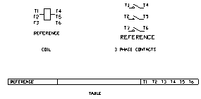
For a NO/NC table symbol: vxNO.dwg, hxNO.dwg, vxNC.dwg or hxNC.dwg
-
The NO/NC table symbols are used for all symbols cross referenced with a normally open / normally closed contact table.
For a BOM / reference table: vxTable.dwg or hxTable.dwg
-
The BOM / reference table symbols are used for all symbols cross referenced next to a BOM / reference table header, rheadh_t or rheadv_t.
For the TABLE row symbol: xtable.dwg
-
The table row symbol is used for all symbols cross-referenced with a table header, RHEADT, instead of a list header, RHEAD. A tabular reference is always drawn down the page.
Elecdes Symbol Naming Conventions
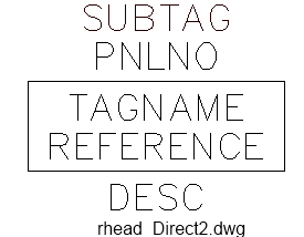
Direct reference symbols
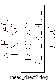
The rhead_Direct1.dwg (horizontal) and rhead_Direct2.dwg (vertical) are direct reference symbols used for a referencing a component anywhere in your project. The direct reference block may be moved at any time and NEWLY GENERATED references will be placed underneath.
Drawing Reference symbols
Drawing reference symbols are used for back annotating to the appropriate entry in reference drawings table for your sheet. File names of drawing reference symbols should begin with Diamd_ (eg: Diamd_Schematic.dwg).
Different component representations (schematic symbol, 1LD symbol, 2D panel block, etc) can use different drawing reference symbols. These can be configured in the cross reference preferences.
Drawing reference symbols will have the following attributes loaded with reference information:
-
TAGNAME: The tagname of the destination device.
-
PNLNO: The destination panel number or location of the remote device.
-
REF_NUMBER: The index of the reference drawing from the Reference Drawings table of that sheet. This number is visible.
-
DRAWING: The file name of the reference drawing.

Directory for cross-reference symbols
The files for these symbols are all found in the following directories:
-
Cross reference control symbols: <EDS>\IMP_RFIN and <EDS>\MET_ RFIN (for metric users).
-
Reference List symbols: <EDS>\IMP_XSYM and <EDS>\MET_XSYM (for metric users).
-
Zone symbols: <EDS>\IMP_CNCT and <EDS>\MET_CNCT (for metric users).
Location on the Menu
-
Cross-reference control symbols can be found on the icon menu.
-
The zone insertion function is started by selecting .
Insertion Procedure
Cross Reference Control Symbol Insertion
Import a materials / reference table on to a drawing.
Attributes of cross reference symbols
For a list of attributes refer to Attributes of Symbols.
Customisation of cross-reference symbols
For information about adding and customising Reference List symbols see Symbol Modification.