How to Change Wire Termination Ordering
Fundamentals
The terminations of each wire will be sorted in the wire schedule.
By default, the terminations of a wire are sorted according to the sheet or drawing name. Multiple terminations on a single sheet or drawing are sorted by position; primarily they are sorted left to right followed by sorting top to bottom.
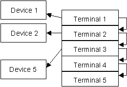
The devices and terminals are then divided into two separate lists, sorted as described above. The first terminal is connected to the first device. Then the first terminal is connected to the second terminal. Then the second terminal is connected to the second device and so on. Multiple terminations on a single device are sorted alphanumerically according to terminal number.
This is illustrated by the following diagram.
If the default sheet number and position termination order is not suitable for a wire, you may use Elecdes termination blocks or Paneldes wire optimisation to specify the required termination order.
-
In the Elecdes schematic drawing, a termination block can be inserted at each termination of the wire. The terminations in the wire schedule will be sorted according to the order number specified in the termination block for each termination.
-
If you have a physical model, in Paneldes, for the devices connected to the wire, you may use Paneldes to sort the terminations of the wire by their physical location.
See How to Optimise the Termination Order for Wires for more information on this procedure.
Also see How to Back Annotate the Paneldes Wire Order in this guide.
Configuring the Wire Order with Termination Blocks
Termination blocks are special control symbols that are placed at each termination of a conductor.
There are two blocks: HSCONX.DWG and VSCONX.DWG for horizontal and vertical conductor orientation.
Termination blocks should be edited in the Global Editor.
-
Run the Global Editor.
-
Select the class TERMINATION.
-
The main list in the Global Editor will show an entry for each wire or cable core (conductor) termination. This is unlike other classes, which only show entries for symbols present in the drawings.
-
Ensure that Auto-insert Termination Blocks is ticked. When the drawings are updated, a termination block will be inserted at the point where each conductor terminates at a component. One block for each entry in the list.
-
The order of the terminations of a wire can be specified by entering an ordered sequence of numbers into the WORDER field of each termination of the wire. This data is stored in the NUMB attribute of the termination block.
If the WORDER field is left blank, or contains the number 0, for all terminations on a wire, then the terminations on that wire will remain sorted by the drawing and position.
-
When the wire schedule is regenerated, the terminations of the wire will then be arranged exactly in the sequence specified by the number in the NUMB attribute of the termination blocks.
-
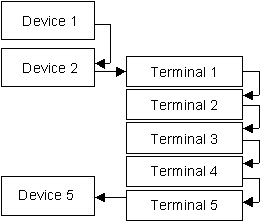
For the example at the top of this topic, this could produce a sequential wiring order similar to the diagram below:
Valid wire termination order numbers
You can specify that a termination should appear in a particular order from either the start of the wire or from the end of the wire.
-
Use increasing positive numbers, for example 1, 2, 3, 5 , to specify the order of terminations from the start of the wire. The termination with the number closest or equal to 1 will become the first termination on the wire.
-
Use decreasing negative numbers, for example -1, -2, -5, -6 , to specify the order of terminations in reverse from the end of the wire. The termination with the number closest or equal to -1 will become the last termination on the wire.
-
You can leave gaps in your numeric sequence.
-
The number 0, or leaving the WORDER field empty, indicates an unordered termination.
-
You can have a mixture of ordered and unordered terminations. Unordered terminations will come after any terminations with positive wire order numbers and before any terminations with negative wire order numbers.
Wire order blocks (worder.dwg) from previous versions of EDS
EDS will read and maintain the wire order from the older wire order block, worder.dwg. The contents of the ORDER attribute will be loaded into the WORDER column in the Global Editor. These blocks are treated as if they were new termination blocks with a single wire order attribute.
See also
The two termination blocks, HSCONX.DWG and VSCONX.DWG, contain other attributes. In total the termination blocks can provide wire termination order, wire labels and crimp specification.
How to add wire labels to the ends of conductors
How to add crimps to the ends of conductors
How to generate connection schedules
How to add and remove termination blocks (CONX) (Elecdes)
How to add glands and insulation information to the cables in single line diagrams (Elecdes)