How to add GLANDS and INSULATION information to the cables in single line diagrams
Fundamentals
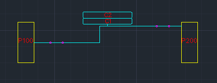
Elecdes allows you to put GLANDS and INSULATION information on your single line diagrams which can be used in materials reporting. Elecdes uses Termination blocks (or CONX blocks) to contain the GLAND and INSULATION information for cable terminations. You can choose different types of GLANDS for each of the terminations e.g. you may have a 10mm gland at one termination and a 15mm gland at the other termination. Piggy-back cable markers allow you to represent multiple cables on your single line diagram as shown in the figure below.
Directory
The catalog files for gland or crimp symbols (CATR.dbf) are found in the following directories: <EDS>\IMP_CAT for imperial and <EDS>\MET_CAT for metric users. You can edit the catalog file to add your entries to it.
Procedure
Click on
 from the menu. Elecdes is designed to add only one termination block at each termination, so this will add only two CONX blocks, one at each end of the cable.
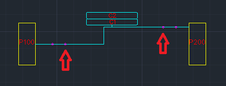
UN-FREEZE the WORDER layer in AutoCAD to see all of the termination blocks as shown in the figure above.
For all the piggy back cable markers e.g. C2, C3, C4 etc. copy and paste the CONX blocks at both ends next to the existing conx block moving towards the centre of the line. The figure below shows the two termination blocks that have been added for cable C2.
Select all of the CONX blocks and click on
 from the menu.
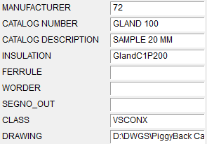
Choose the Elecdes catalog specification for the Glands used for each end of the cable. The catalog information for the glands on each end will come out in GLAND_A and GLAND_B in the cable report and as entries in the materials reports. See the figures below.
Fill in the insulation information for each end of the cable in the INSULATION field. The insulation information for both of the glands will come out in INSULAT_A and INSULAT_B in the cable report. See the figure below.
You need to make sure to uncheck the Auto-insert Termination Blocks option before pressing the button, otherwise you will be asked to delete the extra termination blocks.
Save the drawing file and run Ebase and generate the materials reports and connection reports.
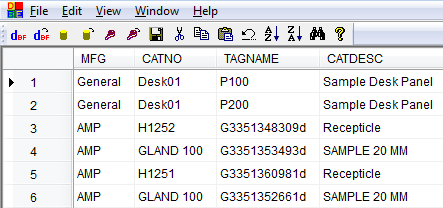
The GLANDS will be listed individually in your materials report with an automatically generated TAGNAME, as shown in the figure below.
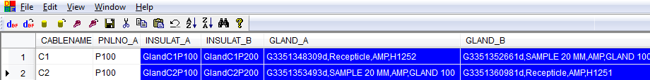
The GLAND_A/B and insulation information INSULAT_A/B are listed for each cable in the cable reports, as shown in the figure below.
See also
Termination Blocks (Elecdes)