Placing Paneldes Components
General
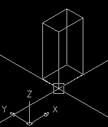
Placing components in Paneldes is done visually with the mouse. The cursor is drawn as a representation of the component you are placing. The graphic below shows the AutoCAD cursor when placing a panel.
This section will discuss placing the various types of Paneldes components.
Normally when placing a component you will be in MODEL SPACE. The AutoCAD command line will indicate what action you should be taking. It will also tell you what options are available.
For example, when placing a panel the AutoCAD command line will be:
Pick insert point <Rightbutton=Menu>,<ESC=Cancel><H=Help><Current Plate = None>
This is indicating that you should pick the insert point for the component with the mouse or by typing it in with the keyboard as a 3D point, e.g. 100,200,0.
You can use the object snap modes (OSNAP) of your CAD package to assist picking the insertion point of the component to align with other features of your model.
| <Rightbutton=Menu> | Indicates that you can click the right button of your mouse to display a menu of options. See the Placement Context menu. |
| <ESC=Cancel> | Indicates that you can cancel placement at anytime by pushing the escape key on the keyboard. |
| <H=Help> | Push the H key to display a help menu with a summary of available options. |
| <Current Plate = None> | Indicates which plate you are currently mounting components on. This will be none if you have not picked a plate. |
Note that the point you pick for your component will always be in the current AutoCAD co-ordinate system, which is called the UCS. If you are not familiar with the concept of co-ordinate systems and the UCS, then you should see the Co-ordinate systems reference section.
To set the UCS to the World Co-ordinate system WCS, choose the Set UCS to World option in the Placement Context menu.
You can use the transparent UCS command by typing an apostrophe prior to the command i.e. 'ucs. You can also use other transparent commands supported by your CAD package.
Aligning the UCS with a Mounting Plate
To align the UCS with a plate in your model, click on the edge of the plate.
-
When picking a plate, the edge of the plate must lie within the aperture box surrounding the cross hair. You can adjust the aperture size via the Placement Context menu.
-
If you are picking a plate in an orthogonal view, i.e. Plan, Front or Side you must have the UCS in a state that allows you to pick entities properly. If you are experiencing difficulty in picking plates in a view use the Set UCS to View option in the Placement Context menu.
Once you have successfully picked a plate, the following dialog will appear:
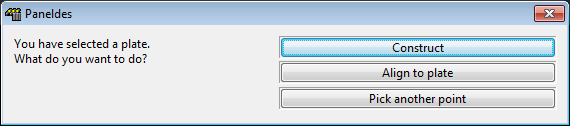
Here you can choose to construct the component at the current position, Align to the plate you picked or Pick another point.
If you choose align to plate, the UCS axes will be aligned with the edge of the plate. The X-axis will be along the bottom edge of the plate and the Y-axis will be along the left edge. The Z-axis will face out of the front face of the plate. See the Plate Dimensions reference section.
If the location specified for the component you are placing does not match the location of the plate you have chosen to align the UCS with, then you will see the following dialog. It is telling you that you may be placing the component in the wrong location.
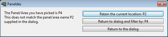
You can choose from three options:
| Retain the current location: | Keep the value for the location that was entered in the component placement dialog. |
| Return to the dialog and filter by the location you picked: | This will go back to the placement dialog but change the location for the component to the location you picked. |
| Return to the dialog: | Go back to the placement dialog without changing any of the data. |
Now that the UCS is aligned with the plate, the co-ordinates will be measured from the bottom left corner of the plate. The movement of the component will be constrained within the edges of the plate. To allow the component to move beyond the edge of the plate, you must un-tick the Constrain to Plate entry on the Placement Context menu.
You can now rotate the component and offset it, relative to the cursor position. See the Placement Context menu and the Placement Keyboard Shortcuts for details.
When placing terminal strips, if you pick a plate that is taller than it is wide (e.g. a vertical DIN rail) then the strip will be rotated automatically by -90° so that it is placed vertically on such a mouting plate.
Once you are happy with the position, click the left mouse button to place the component or type in a 3D point and push enter.
Placing Raceway
If you are placing a route segment, there are additional options that do not apply to other components, like Devices and Accessories.
Mounting Raceway Segments on Plates
You may mount route segments on plates in a similar fashion to other components as discussed above. However there are some additional options that apply only to route segments.
When you have picked a plate and chosen to Align to Plate you will be presented with an additional dialog shown below.
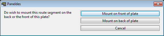
You can choose to mount the route segment on the front or the back of the plate.
Paneldes will automatically set an offset value of half the width of the route segment down the Z-axis.
Auto Alignment and End Snap
Route placement can automatically snap a route segment to any available placed route segment end. To use this feature, move the mouse over an existing route segment end so that the end is within the aperture box of the cursor. You will notice that the UCS will align with the existing route segment while the end of it is within the aperture box. You can switch the end of the route segment that you are attaching with the E key, as well as rotating it using the rotation keys. See the Placement Keyboard Shortcuts and Placement Context menu for a full list of keys and menu options.
Picking Raceway Segment Lengths
If you are placing a route segment length you have the option of picking the length with the mouse. If you have chosen to place a route segment length without a fixed length value then you will be asked to pick the length regardless of the Always Pick Length setting. If, however, you have typed in a length value and do not wish to pick the length, you must un-tick the Always Pick Length option on the Placement Context menu.
Picking the length takes place after you have picked the position of the route segment. You may only pick a positive value for the length and the picking direction will be along the UCS X-axis. If you wish to type in the value of the length push the T key, then type the required length into the dialog.
You can use the object snap modes (OSNAP) of your CAD package to assist picking the length of the segment to align with other features of your model.
Instead of picking with the mouse or typing the length, you can also type in the position at which you want the end of the route segment to be located. Note that Paneldes will only use the X component of the point you type, as the route must lie along the X-axis.
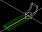
Paneldes will AUTOSNAP to the length required to connect to another segment if your mouse is located over that target segment end. The images below illustrate this. Note the Paneldes will only use the X component of the end point that you pick.
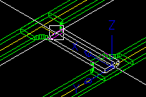 | 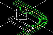 |
Splitting a Raceway Length Segment with a T-Section or X-Section
If you have an existing raceway length segment and wish to split it in half with a T-Section or X-Section, click the left mouse button on the centre of the raceway length segment that is already on the drawing. The T or X Section you are placing will then be constrained to the length segment and you will be able to slide it up and down the length.
You can then pick the position to split the length segment and construct the T or X Section by clicking the left mouse button again. If you wish to pick a different length segment to split, while you are sliding up and down a route segment length, push the ESCAPE key.
While the T or X section is constrained to the length segment, Paneldes will autosnap its position along that length to align with any other segment endpoint that you move your mouse over.
You can use the object snap modes (OSNAP) of your CAD package to assist picking the position of the T or X section along the length segment to align with other features of your model.
A raceway segment that is split with a T or X section becomes two segments in the drawing. The original segment is resized to become the first segment and a new segment is created as the second segment. The new segment inherits the catalog configuration of the original segment. The name of the new segment is based on the name of the original segment with the new objects entity handle added so the segments still have unique names. For example, if the raceway TRAY001 is split by a T section, the new segments are named TRAY001 and TRAY001(A7), where the (A7) is the entity handle of the second split part enclosed in brackets.
Picking Bar Lengths
If you are placing a bar (link or bridge bars, bus bars, or earth bars), you have the option to place a bar with a length specified from the catalog, or you can pick the length of the bar in the drawing.
If you have chosen to place a bar without a fixed length value, then you will be asked to pick the length regardless of the Always Pick Length setting. If, however, you have typed in a length value and do not wish to pick the length, you must un-tick the Always Pick Length option on the Placement Context menu.
Picking the length takes place after you have picked the position of the bar. You may only pick a positive value for the length and the picking direction will be along the UCS X-axis. If you wish to type in the value of the length push the T key, then type the required length into the dialog.
You can use the object snap modes (OSNAP) of your CAD package to assist picking the length of the bar to align with other features of your model.
Instead of picking with the mouse or typing the length, you can also type in the position at which you want the end of the bar to be located. Note that Paneldes will only use the X component of the point you type, as the bar must lie along the X-axis.
Placing Plates
Placing a plate is quite different to placing other Paneldes components. When picking the position of the plate you will see that the cursor drawn to represent the plate has an arrow facing in the direction of the front of the plate. You will initially be able to move the plate in two directions. If, for example, you have chosen to mount the plate so that it faces the front of the panel, then the UCS will be set such that you can move the plate backwards and forwards and up and down within the panel. If you wish to move the plate laterally in the panel you need to choose the Switch Plate UCS option, in the Placement Context menu.
This will keep the position you had when you pushed the right mouse button but will spin the UCS to allow you to pick in the other direction. When you are happy with the position of the plate, click the left mouse button. You will be presented with the following dialog:
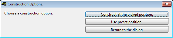
The dialog provides three options:
-
Construct at the Picked Position: The plate will be constructed at the position you have picked.
-
Use Preset Position: The plate will be constructed at the position specified in the Plate Dialog.
-
Return to the Dialog: Go back to the dialog. Note that this option will keep the picked position, so you can adjust it.