How to Optimise the Termination Order for Wires
General
Schematic drawings show the terminations for a wire but often lack the information to show the optimum order in which the terminals should be connected to minimise the length of wire required. Without any additional information, Ebase will place wire terminations in the order by sheet or drawing name, followed by position.
Paneldes Wire Optimisation can determine, from a panel model, the optimum order in which to connect a wire for the shortest length.
Note: Elecdes has the option to specify the wire termination order in the schematic drawings without requiring or using a Paneldes 3D model. More information is provided below under the heading Forced wire termination order from schematic drawings.
Paneldes Wire Optimisation
Paneldes wire optimisation re-orders the data and the records of the wire schedule report so that the terminations for each wire are listed, in pairs, in the optimum order. Wire optimisation modifies the report only for wires that have three or more terminations. Wires with two or one termination are unmodified.
Paneldes wire optimisation is an optional process that is additional to conductor route optimisation. Optimisation for wires is chosen during the route optimisation procedure.
Procedure
Enable the Optimise Wire Lengths option on the Routing: Wires page before Routing and Viewing Wires. Each time you route wires it will run the "Optimise the wire termination order" algorithm.
-
Select the Cable Manager entry from the Routing: Wire and Cable menu.
-
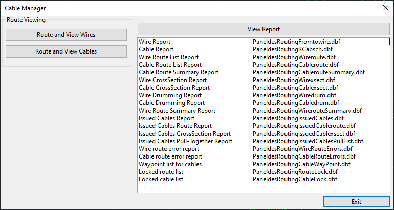
You will be presented with the Cable Manager Dialog shown below.
-
The Generate/Update reports group, at the top of the dialog, allows you to specify which type of reports you wish to generate. Tick the box for Wire reports.
-
Click the Generate/Update Reports button.
This will begin the Route Optimisation function, which includes the option to optimise the wire termination order.
-
Paneldes may automatically extract data from the drawing file and then suggest connection settings that should be used for routing your model. You should click yes to accept the suggested settings unless you know the settings you have are more accurate.
-
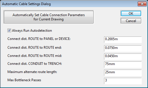
You will then be presented with the automatic settings dialog.
-
The settings to use for routing are listed on the dialog.
Paneldes can suggest some of these values at your request. See Automatically Suggested Connection Settings.
-
Tick the box Optimise Wire Lengths.
-
Click the OK button to begin the wire optimisation.
-
When the wire optimisation begins, you will be shown a progress bar, which allows you to cancel the optimisation at any time.
-
When the wire optimisation has completed it will display a summary dialog, similar to the route optimisation summary dialog.
-
When wire optimisation has completed the route optimisation procedure will continue, and will find the optimum route between each pair of terminals.
Forced wire termination order from schematic drawings
In Elecdes, it is possible to specify the wire termination order in the schematic drawings using termination blocks inserted at each termination of the wire. The terminations in the wire schedule will be sorted according to an order number specified in the termination block for each termination. See How to Change Wire Termination Ordering.
If the schematic drawings contain wire termination order information, then the termination order numbers are written into the wire schedule report in the FORCE column. If the FORCE column contains non-zero wire termination order numbers then the Paneldes wire optimisation will adhere to the specified order. (The order for forced terminations should remain unchanged since Ebase will already have reported those terminations in the specified order).
Termination order values should appear in pairs, for example "0,0" or "7,8". The first number refers the termination in the _A columns of the report and the second number refers to the termination in the _B columns of the report.
Positive termination order values, e.g. 1, 2, 3..., specify that terminations should appear at the start of the wire. Negative termination order values, e.g. -3, -2, -1, specify that terminations should appear at the end of the wire. The value 0 does not specify any termination order. If the FORCE column contains a zero for a termination then Paneldes can re-order that termination.
You can force the order of the terminations at the start of a wire using positive numbers and at the end of a wire using negative numbers, leaving only the terminations in the middle of the wire for Paneldes to optimise.
Fixing the wire termination order once optimised
Ebase report generation always erases and recreates the wire schedule report. If a wire schedule is re-generated from Ebase any Paneldes wire optimisation will be lost, since Paneldes only rearranges the data and records of the report file.
Ebase has the option to "back annotate" the results of the Paneldes wire optimisation to the schematic drawings.
Once the wire optimisation results are back annotated to the schematic drawings, the order of the terminations becomes fixed, as follows: Ebase will always write the terminations in the order specified by the order numbers found in the schematic drawings. Ebase will write those order numbers into the FORCE column. If the Paneldes wire optimisation is re-run, it will adhere to the order numbers in the FORCE column. The termination order is now fixed.
New terminations that are added in the schematic drawings are not fixed and will be appended to the end of the current termination order.
Back annotating the wire termination order to the schematic drawings
Back annotating the Paneldes wire optimisation takes the temporary wire termination order values from the FORCE column, e.g. "$3,$4", and writes these numbers into the termination blocks (CONX) in the schematic drawings. New termination blocks will be inserted if required.
-
Run the Paneldes Wire Optimisation, as described in the procedure above.
-
Ensure that none of the schematic drawings from the current project are open in Elecdes as this will prevent Ebase from writing information to them.
-
Run EBASE.
-
Tick the box Back Annotate Paneldes Wire Order.
It is not necessary to tick the box for Connection Reports. However, if the connection reports are to be generated, the back annotation of the wire order will occur before generating the reports.
-
Click the button Compile Reports.
-
Ebase will find all of the temporary wire termination order values in the FORCE column and write those values into the termination blocks in the schematic drawings.
-
Further generation of the wire schedule report from Ebase, or execution of the Paneldes wire optimisation, will adhere to the wire termination order specified in the termination blocks. The termination order is now fixed.