How to Draw Ladder for Control Circuits
Fundamentals
The ladder construction function is used to draw arrays of line segments and wire connect dots (if required) on your drawing. Ladder of any size, orientation and number of rungs may be created. Subsets of a full ladder may also be created.
The ladder function will create the following ladder and sub-ladder arrays:
| Ladder (with rungs). |  |
| Ladder rails. |  |
| Ladder Rungs. |  |
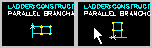
| Parallel branch. | 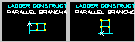 |
| Sub ladder. | 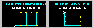 |
Procedure
-
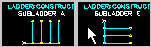
Select from the menu.
-
The various styles of ladder will be displayed in an icon menu that displays the icons shown above. Choose the style of ladder you wish to insert.
Ladder, Ladder Rails and Ladder Rungs Procedure
-
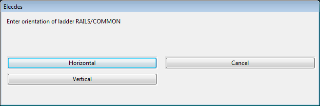
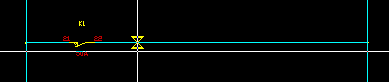
Choose the orientation of the ladder rails.
-
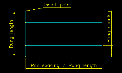
Pick the insert point of the upper or left rail of the ladder.
For rungs-only this should be on the upper / left rail which the rungs are being placed upon.
-
Pick the distance between the rails, the length of the rungs. Press "T" if you want to type in the value in drawing units.
-
Pick the distance between the rungs. Press "T" if you want to type in the value in drawing units.
-
For ladder or rungs only: Enter the number of rungs.
-
OR, for rails only: Pick the length of the rails. Press "T" if you want to type in the value in drawing units.
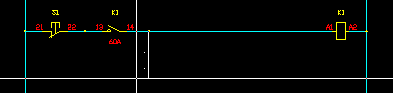
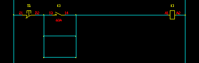
Sub-Ladder Procedure
-
The icon menu of ladder styles includes an icon for a horizontal sub-ladder and a vertical sub-ladder.
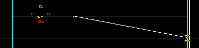
Choose the sub ladder orientation you require.
-
Pick the connection point for the common rail of the sub-ladder. The point should be on an existing rung with the same orientation as the rungs in the selected sub-ladder icon. The command line will remind you of which orientation you have selected.
-
Pick the connection point of the first rung of the sub-ladder. This point also defines the distance between the rungs. Press "T" if you want to type in the two values, in drawing units.
The point should be on the rail of the existing ladder.
-
Enter the number of rungs (in the example below – 2).
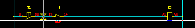
Parallel Branch Procedure
-
The icon menu of ladder styles includes an icon for a horizontal parallel branch and a vertical parallel branch.
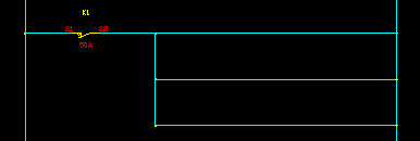
Choose the branch orientation you require.
-
Pick the connection point of the upper or left rail of the branch. The point should be on an existing rung with the same orientation as the rungs in the selected branch icon. The command line will remind you of which orientation you have selected.
-
Pick the distance between the rails, the length of the rungs.
-
Pick the distance between the rungs. Press "T" if you want to type in the value in drawing units.
-
Enter the number of rungs (in the example below – 2).
See also
How to draw conductors for a circuit.
How to draw a transformer link to a 3 phase bus.