How to Change Between Bar Link, Wire Link and Wire
Any wire that is connected between two terminals on the same terminal strip can be shown as a bar link (bridge bar) or wire link.
The Wiring Diagram Generator uses user configurable rules to determine which conductors should be represented as bar links or bridge bars, which conductors should be wire links and which conductors should be represented as standard wires.
A wire that is connected between two terminals on the same terminal strip but that is connected to opposite sides of polarised terminals in the schematic will not be shown by default as a bar link or wire link, since that would cause one end of the link to appear to be connected to the wrong side of the polarised terminals.
NOTE: You can specify that a wire represents a bar link directly from the schematic by setting the RSTATUS attribute or catalog column of the wire to the text "BARCOND". You can specify that a wire represents a wire link directly from the schematic by setting the RSTATUS attribute or catalog column of the wire to the text "WIRELINKLEFT" or "WIRELINKRIGHT". Wires marked as BARCOND, WIRELINKLEFT or WIRELINKRIGHT will force the wire to draw as a link even if it is connected to opposite sides of polarised terminals. RSTATUS is a new attribute and would need to be added to wire marker symbols from EDS versions prior to 7.3.
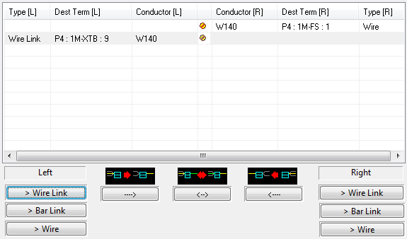
If some of the conductors are not assigned to the type of link that you require, you can use the following controls, which appear under both the left and right side of the conductor list on the T-Strip Edit dialog, to change the link type.
Procedure
-
Open the T-Strip Edit dialog of the Wiring Diagram Generator and select the terminal strip that you want to edit.
-
Select the terminal that is connected to the link you want to edit.
-
In the conductor list on the right of the dialog, select the row containing link that you wish to change.
-
To change the type of a link that is in the left side of the list, use one of the three buttons under the left side of the list.
To change the type of a link that is in the right side of the list, use one of the three buttons under the right side of the list.
If you attempt to change a wire that is not a link into a wire link or bar link, then the Wiring Diagram Generator will display a warning to let you know the operation was invalid.
NOTE: If the diagram is regenerated for this terminals strip then the choice of wire or bar link will remain as the manual choice by default.
Changes to the rules controlling the automatic choice of the type for conductor links and link placement on a terminal strip are only used when there is no existing terminal strip diagram.
To load conductor link types from the schematic or loop drawings according to the rules in the Wiring Diagram Generator preferences you should completely erase the existing terminal strip diagram from the drawing.
If you never edit the link type on terminal strips then you can choose to always reload the type when regenerating the terminal strip in the preferences for Wirediag. See Properties to Retain When Refreshing Wiring Diagrams.
Conductor arrangement rules
For information about the user configurable rules the Wiring Diagram Generator uses to assign conductors as bar links or wire links on a terminal strip see the section Configure Wire and Bar Links Between Terminals.
Example of changing the type of a link
The conductor on the left side in the second row has been changed to a wire link.