Configure Wire and Bar Links Between Terminals
Any wire that is connected between two terminals on the same terminal strip can be shown as a bar or wire link. However, a wire that is connected to opposite sides of a polarised terminal on a strip cannot be shown as a link as it would cross from one side to the other.
Links between terminals in a terminal strip can be drawn as either:
-
External wire links looped to each connected terminal on the left or right side of the strip.
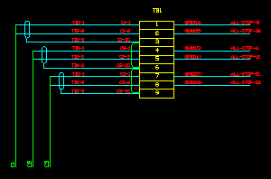
-
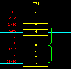
Bar links inside the terminal symbol boxes with dots to show connection to each terminal
Both types of links can be configured individually using the controls shown above. Both groups of controls work in a similar manner.
Links between hybrid terminals are always shown as normal wires as each hybrid terminal is inserted individually and therefore may not be aligned for drawing a wire or bar.
Using both wire and bar links together
If both bar and wire links are enabled:
-
Wires that are marked as bar links in the schematic will be shown as bar links.
-
Wires that are marked as wire links in the schematic will be shown as wire links.
-
Bar links will be used for linking terminals until there are more links than the number of bars that has been configured.
-
Wire links will be used for the remaining links between terminals until there are more links than the number of wire links that have been configured.
-
A wire that is connected between two terminals on the same terminal strip but that is connected to opposite sides of polarised terminals in the schematic will not by default be shown as a bar link or wire link since that would cause one end of the link to appear to be connected to the wrong side of the polarised terminals.
-
All remaining links will be drawn as normal conductors.
-
If you set Max Bars to 0 then the Wiring Diagram Generator will not assign any conductors to bars automatically; however, any conductors specifically identified as bar links in the schematic drawings will be shown as bars.
This enables you to control which are bar links and which are wire links directly from the schematic.
-
If you set Max Links to 0 then the Wiring Diagram Generator will not show any conductors as wire links automatically; however, any conductors specifically identified as wire links in the schematic drawings will be shown as links.
This enables you to control which are shown as wire links and which are shown as standard wires directly from the schematic.
NOTE: You can specify that a wire represents a bar link directly from the schematic by setting the RSTATUS attribute or catalog column of the wire to the text "BARCOND". You can specify that a wire represents a wire link directly from the schematic by setting the RSTATUS attribute or catalog column of the wire to the text "WIRELINKLEFT" or "WIRELINKRIGHT". RSTATUS is a new attribute and would need to be added to wire marker symbols from EDS versions prior to 7.3.
Max terminals jumped
Both types of links can be configured so that a link can only jump a specified number of terminals. All links that are separated by more than the specified number of terminals will be drawn as normal conductors. To restrict the links to consecutive terminals only, choose 0 as the maximum number of terminals that can be jumped.
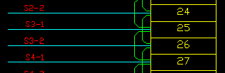
The maximum number of links refers to the number of links that can be stacked parallel to each other without overlapping. The following examples show two levels of stacked wire and bar links: For wire links you can choose up to eight levels. For bar links you can choose up to twenty levels. The number of bar links is intentionally large for bars to enable you to show links of any type as bars and avoid showing any wire links, if desired. See the information above Using both wire and bar links together for the effect of changing the maximum number of either wire or bar links. Different wire names represent one bar If you use different wire names on each segment of a conductor when really it is one bar then you should tick the box Different wire names represent one bar. The Wiring Diagram Generator will still treat the conductors as separate bars but, by ticking this option, you specify that the different bars should align at their endpoints so they appear as one solid bar in the terminal strip diagram. If you ensure that you use the same wire name for all wire markers that represent a single bar then you should clear the tick from the box Different wire names represent one bar. The Wiring Diagram Generator will then ensure that no two bars occupy the same slot even at their end points.
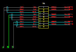
Wire links can be Wire links can be placed on either the left or right side of the terminal strip. If there is more than one stacked level of wire links, they will all be placed on the chosen side. The following example shows the wire links placed on the right side. You can specify that a wire represents a wire link and that it should appear on the left side of the strip directly from the schematic by setting the RSTATUS attribute or catalog column of the wire to the text "WIRELINKLEFT". Similarly, you can specify that a wire represents a wire link and that it should appear on the right side of the strip directly from the schematic by using the the value "WIRELINKRIGHT". Wires marked as WIRELINKLEFT or WIRELINKRIGHT will force the wire to draw as a link even if it is connected to opposite sides of polarised terminals. The wire link side option remains enabled even when The settings under the title Link Position enable you to control the offset of the wire links from the edge of the terminal strip. These are parametric distances. If you change the values, the wire link lines will change position. The settings should be in drawing units. Dimension V specifies the distance from the side of the terminal strip to the first wire link. Dimension U specifies the distance between stacked wire links. The settings under the title Bar Position enable you to control the offset of the bar links from the edge of the terminal strip. These are parametric distances. If you change the values, the bars will change position. The settings should be in drawing units. Dimension Y specifies the distance from the side of the terminal strip to the first bar link. Dimension X specifies the distance between stacked bar links. Wire and bar links can be disabled individually by clearing the Use Wire Links and Use Bar Links checkboxes. NOTE: Disabling the drawing of wire links or bar links via these options will cause Wirediag to ignore the schematic RSTATUS values of "BARCOND", "WIRELINKLEFT" and "WIRELINKRIGHT", and draw those wires as normal wires. These settings can be found on the Terminal Strips tab page of the wiring diagram settings dialog.Number of links

Aligning or separating bar links - Different wire names represent one bar


Wire link side
Position of wire links
Position of bar links
Disabling links