Appearance of Cables
Orientation and position of cable lines
Cables attached to a terminal strip or device can be drawn in one of three configurations. Select any option to the right of the cable configuration that you want.
If the cables are to be drawn in one of the three configurations, you can then choose whether or not there is a chamfer where each cable core or conductor joins the cable line.
Join cable lines between strips
Join cables between colinear strips
Cable lines can be joined between different terminal strip or device wiring diagrams when those diagrams are aligned horizontally or vertically within a specified tolerance. Tick the box to allow cable lines to be joined between diagrams.
Cable tails will not extend across devices that do not connect to those cables and, conversely, will extend across devices that do connect to the cable.
Specify the tolerance for misalignment of terminals in one column or row such that cable lines will be joined for all of the terminals positioned within that tolerance.
For example, if you have three diagrams arranged vertically down the page and the setting is 50mm or 2", then the cable lines will be joined down the three diagrams for all of the terminals that are positioned no more than 50mm or 2" away from the first terminal horizontally. Each column of terminals that is more than 50mm or 2" from another column of terminals will have another group of joined cable lines.
Join cables between parallel strips
Cable lines can be joined between parallel strips by ticking this box. The distance between the parallel strips must exceed the Colinear strip tolerance distance. The cable lines between any two parallel strips will only join if the cable line from each strip is configured to draw towards the other strip.
Join non-adjacent cables via drawing margins
Any cable lines that could not be joined between colinear or parallel strips (due to the presence of other strips or the configuration of the cable lines) can be forced to join in a margin around the outside of the wiring diagram.
Tick the box to allow joining of non-adjacent cables and set the size of the margins around the bounding box of the wiring diagram that can be used by the Wiring Diagram generator to join these cable lines.
Fit Cable Symbols
If you tick the checkbox Fit Cable Symbols then Wirediag will ensure that cables are placed no closer together than the specified Minimum symbol spacing. You can use this option to ensure that there is always sufficient space to fit the attributes around the cable symbol without the symbols and their attributes overlapping.
Sub-options allow you to choose how a cable line is shifted if its original top position is within the specified minimum spacing. You have options to only place an offset in the cable line, or to shift the line to align with another of its cores/conductors.
Minimum Symbol Spacing
Enter in drawing units the minimum distance that you want between each cable symbol. Wirediag will use your choice of one of the options described below to ensure that the cables are no closer to each other than the spacing that you enter.
Do not fit by using lower cores
This is the default option. If you choose this option then Wirediag will start the cable line at the first core/conductor of each cable, then create an offset in the cable line if required to ensure the cable symbols are at least at the minimum spacing.
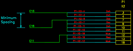
In the figure below, all of the cable lines are connected to the first core/conductor and an offset is required in all of the lower cable lines to ensure that the cable symbols are at the user specified minimum distance from each other.
Use any lower core to fit cable symbol
If you choose this option then Wirediag will try to fit the cable symbols at the specified minimum spacing by starting at any one of the lower cores/conductors if it exists at user specified minimum distance from the previous cable.
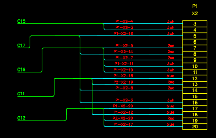
Comparing the figure below with the previous figure, note that cable C17 has been shifted to align with its second core/conductor, which is at least minimum distance apart from C15. Cable C16 does not fit at any of its cores/conductors, so it is aligned at its lowest core/conductor and the cable line is further offset to achieve the minimum spacing from C17.

Use any core, prioritise lowest core
If you choose this option then Wirediag will try to fit the cable symbols at the specified minimum spacing by starting at any one of the lower cores/conductors if it exists at user specified minimum distance from the previous cable. However, the lowest core/conductor will get highest priority over any other core/conductor. If the lowest core/conductor would also overlap with another cable then Wirediag will also try fitting the cable at its intermediary cores/conductors.
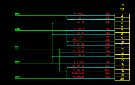
Comparing the figure below with the previous figure, note that cable C17 has been shifted to align to its lowest core/conductor and has been moved to a lower position than other cables ( i.e. C16 and C11 now fit above C17 ).
Use only lowest core to fit
If you choose this option then Wirediag will try only the lowest core/conductor to fit a cable that cannot fit in its top position. If the cable still does not fit at the lowest core/conductor then it will be offset to achieve the specified minimum spacing.

TWIN cables use lowest core
Twin cables refer here to two cables that have the same number of cores/conductors and those cores/conductors are connected to the same terminals.
If you tick the checkbox TWIN cables use lowest core then Wirediag will always fit the twin cables by aligning one cable with top core/conductor and the other cable with the lowest core/conductor.
Size of cable lines
The settings in the Cable Tail - Spacing group enable you to control the size of the cable lines in the terminal strip and wiring diagrams. These are parametric sizes. If you change the values, the cable lines will change in size.
The settings should be in drawing units.
Additional conductor sizes can be configured for the connections to the terminals, see Size and Scale of the Conductors.
Cable line size ( R )
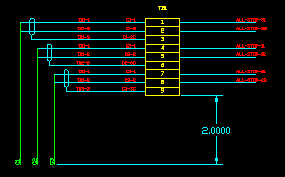
The cable line size specifies how far the cable line extends vertically below or horizontally to the side of the terminal strip or wiring diagram. The choice of cable orientation is described above.
Cable offset ( L[1] and L[x] )
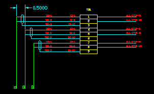
The cable offset specifies the separation between the cable lines for different cables.
L[1] refers to the first cable. L[x] refers to all following cables.
Cable screen width ( W )
The cable screen width specifies the width of the ellipse representing a cable screen. The other dimensions of the cable screen are calculated from this value.
Cable screens can be configured, see Cable screen configuration.
Cable symbol
A cable symbol is placed at the bottom of the cable line. The default cable symbol shows only the cable name.
Optionally, the destination panel can be shown next to the cable name, see Wire and Termination Annotation. Other attributes can be added to the symbol, see Wiring Diagram Symbols and Attributes.
These settings can be found on the Cables tab page of the wiring diagram dialog.
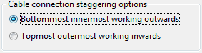
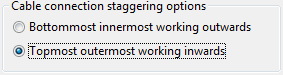
Cable connection staggering options
Wiring diagram provides you options for staggering the cable collectors according to your project's requirements. These can be found in the Cable connection staggering section of the Cables tab of the wiring diagram dialog. You can try these options to see the difference in the wiring diagrams generated for a terminal strip and select the best suited option for your project requirements.
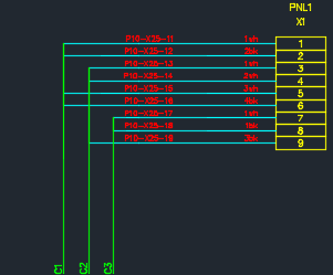
Bottommost innermost working outwards
If you choose the Bottommost innermost working outwards option, Wirediag will start by drawing the conductor connected to the bottom terminal as the innermost cable, then place the next available cable collector at the next outer position. This is set as the default option for the wiring diagram, the output would be like the figure shown below.
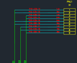
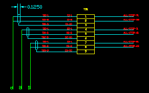
Topmost outermost working inwards
On the other hand, if you choose the Topmost outermost working inwards option, Wirediag will start by drawing the conductor connected to the top terminal as outermost cable, then place the next available cable collector at the next inner position. The figure below shows the output for the same terminal strip as above, with the topmost outermost option selected in preferences. On comparing it with the previous figure, notice that the cables have been drawn starting from the topmost terminal drawn at the outermost and then working inwards.