Leader Construction Sizes
Size of Conductor Leaders
The settings in the Leader Construction Sizes group enable you to specify the size of the symbols used to represent the conductors connected to a terminal. These are not parametric sizes. They are used to specify the size of the symbols so that the Wiring Diagram Generator can draw the cable lines correctly joined to these conductor symbols. If you change the symbols then you should change these values to reflect the size of the new symbols. If you do not customise these symbols then you will not need to change any of these settings.
The three pairs of A and C sizes apply to the three types of diagrams: terminal strip diagrams, wiring diagrams for devices and wiring diagrams drawn from templates.
The settings should be in drawing units.
Additional conductor sizes can be configured for cable lines, see Appearance of Cables.
Leader cable core mode
There are two styles provided to show two conductors connected to a single terminal. By default Style 1 is selected.
Style 1 uses wdLC2 / wdRC2 symbols. Style 2 uses wdLC2C / wdRC2C symbols. This choice lets Wirediag know whether the distance C must be applied below the insertion point (style 1) or centered about the insertion point (style 2).
Leader line length - dimension A
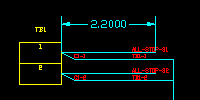
Specify the length of the leader lines in the conductor symbols.
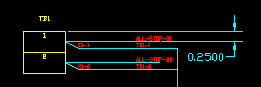
Leader line separation - dimension C
Specify the distance between two leader lines in the conductor symbols.
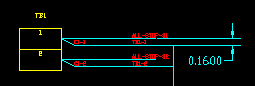
Leader line offset - dimension B
Specify the insertion point for the conductor symbols as an offset from the top of the terminal symbol.
By default the conductor symbol is centred on the terminal symbol.
To specify a specific distance to insert the conductor symbol, clear the Center B box. You can then edit the offset for the conductor symbol.
Wires shown above cores
By default Wirediag will place cable cores/conductors above wires when there are two or three conductors connected on one side of a terminal. Tick the checkbox Wires shown above cores if instead you want the wires to be shown above the cable cores/conductors.
These settings can be found on the Leaders tab page of the wiring diagram dialog.