Wire and Termination Annotation
Wire Annotation Visibility group
You may select the wire annotation that will be visible in the wiring diagram.
Each of the four annotation attributes is configured independently. The four attributes are named specifically from previous versions of EDS but you may now configure any of the four attributes to show any available annotation. The Wire annotation is configured separately for: internal wires (inside one panel), external wires (from another panel), and cable cores/conductors.
When you click on an attribute in the list, the current configuration for that attribute is shown for internal wires, external wires and cable cores/conductors in the boxes to the right of the list.
Configure Wire Annotation
To configure the values to be used for the wire annotation attributes, select the attribute to configure from the list, then click on either the button, the button or the button. Each will display a configuration dialog for the attribute for that type of wiring.
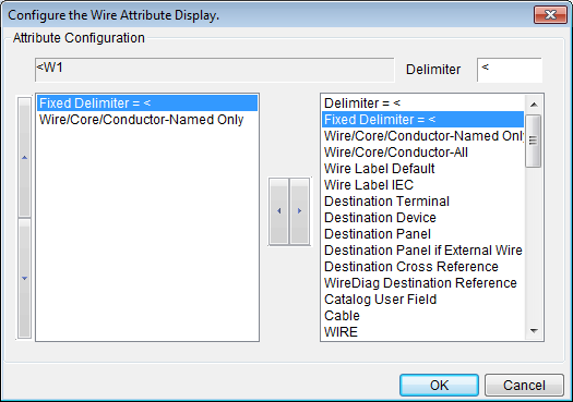
In the left list the configuration for the attribute is displayed. In the right list items that can be used to compose the attribute are displayed. To add an item to the attribute configuration, select the item and click the [<] button. Similarly, to remove an item from the attribute configuration select it from the left list and click the [>] button.
The order of items in the attribute configuration can be altered by selecting the item to reorder from the left list and clicking the up and down buttons to move it up and down in the list. The up and down buttons are located on the extreme left of the dialog.
In addition to the following specifically named items of data, the entire field list of the conductor reports (wire schedule or cable core(conductor) schedule) is available. See the description below.
Attribute Configuration Example
At the top of the dialog is a box that shows an example of what the attribute might contain based on the current attribute configuration. The example is updated each time you add or remove an item from the configuration.
e.g. If the current configuration is "Destination Panel" "-" "Destination Device", then the configuration example will display: "P1-D1".
Delimiter = xxxx
Fixed Delimiter = xxxx
This option enables you to place a delimiter of your choice between any other two items. Enter the delimiter symbol into the Delimiter [ ] edit box. The current delimiter symbol will be shown in the "Delimiter = xxxx" entry. Click the [<] button to add the delimiter to your current configuration for the attribute.
There are two types of delimiter available, standard and fixed:
-
The standard delimiter will be omitted if one or more of the data items that it separates are blank attributes.
-
The fixed delimiter will always be present, regardless of the presence or absence of data surrounding the fixed delimiter.
Wire/Core/Conductor-Named Only
This option refers to the wire or cable core (conductor) name entered in the conductor marker attached to each named conductor in the schematic drawings.
If you want the wire or cable core (conductor) name to appear in the attribute, add this item to the attribute configuration.
Wire/Core/Conductor-All
This option is the same as the "Wire/Conductor/Core Named Only" option with the exception that internally generated wires will also be displayed.
During the interconnection analysis, Ebase will assign default numbers to any conductors that do not have a wire or cable core (conductor) marker in the schematic drawings. This number will appear as the wirename in the Ebase wire schedule for unnamed wires.
The default conductor name is composed of a six digit number, unique for each identifiable conductor found in the project, enclosed in curved brackets: "(??????)", e.g. (000123).
If you want both named wires and cables and the internally generated wire numbers to appear on the wiring diagram, add this item to the attribute configuration.
Wire label Default
Wire Label IEC
The wiring diagram program can display a ferrule (wire label) using the same format as the ferrules (wire labels) in nnFERR.DBF reports. For more information on these reports refer to: Ebase
You may select:
-
Wire Label Default: The wirename OR any ferrule label manually entered to the schematic/loop.
-
Wire Label IEC: <From Device> / <wirename> / <To Device>.
Only one type of ferrule (wire label) may be placed on each wire, IEC or Default.
For the Default Ferrule, ferrule markers can be inserted on conductor lines on schematic drawings to set the ferrule or wire label for each termination of a conductor. The given ferrule (wire label) is placed in the wire or cable core (conductor) schedule at the correct termination. [If no ferrule marker is available for a termination, the conductor name is used as a default ferrule (wire label).]
If you want the IEC or Default Ferrule (wire label) to appear in the attribute, add this item to the attribute configuration.
This item applies to wires and cable cores (conductors).
Destination Terminal
Destination Device
Destination Panel
The destination items indicate the location of the termination at the other end of the conductor. The item "Destination Device" includes both devices and terminal strips at the destination of the conductor.
If you want the destination information to appear in the attribute, add one or more of these items to the attribute configuration.
e.g. If the current configuration is "Destination Panel" "-" "Destination Device", then if a conductor was terminated at a device named "D1" in a panel named "P1" the attribute would contain "P1-D1".
The item "Destination Device" refers to the name of the device or terminal strip. The wiring diagram generator can replace this name for you with an arbitrary alias (TAGALIAS) that refers to the component. This is described in the section Use an Arbitrary Reference for Labelling Connections. Wherever you wish to show the arbitrary alias (TAGALIAS) in the connection annotation, choose "Destination Device" from the list.
Destination Panel if External Wire
This option is the same as the "Destination panel" option with the exception that the panel name is only shown when the wire terminates externally to the panel. i.e. The destination panel is different to the source panel.
Destination Cross Reference
Show the reference of the destination termination, the same as it appears in the connection schedules for the destination termination. This is a reference to the destination termination as shown in the schematic.
The reference is enclosed in square brackets by default e.g. "START1:11 [sheet1 / E.5]"
e.g. For device terminal "START1:11", drawing reference "sheet1 / E.5" and the default brackets "[" and "]", the resulting text will be "START1:11 [sheet1 / E.5] ".
If you want the drawing cross-reference to appear in the attribute, add this item to the attribute configuration.
Wirediag Destination Reference
You can choose the Wirediag Destination Reference to append the reference to another wiring diagram (i.e. the reference between wiring diagrams and terminal strips) to your wiring diagram information.
If the Back annotate references to the Reference Drawings table setting in the cross reference settings is enabled, then a drawing reference symbol will be inserted instead of the destination reference text. The drawing reference symbol indicates that the adjacent wire terminates on the reference drawing in the reference drawings table for this sheet.
If the wiring diagram for the destination has not been drawn and added to the project then this reference between wiring diagrams cannot show the destination reference. Instead a placeholder "[WDXRF:...]" will be shown in its place. When all of the diagrams have been created and added to the project you can refresh the diagrams to replace the reference placeholders with the references to diagrams that can now be found.
Catalog USER field
The data from the USER field of the catalog specification for the conductor can be displayed on each conductor line.
If you want the catalog user data from the conductor to appear in the attribute, add this item to the attribute configuration.
Cable
This option refers to the cable name entered in the cable marker attached to the conductor in the schematic drawings. The cable item will be blank if the schematic conductor is a wire.
If you want the name of the cable, if a cable is connected, to appear in the attribute, add this item to the attribute configuration.
This is not the name of each core or conductor inside the cable. For the core (conductor) name, see the two "Wire/Core/Conductor" options described above.
Other conductor schedule fields
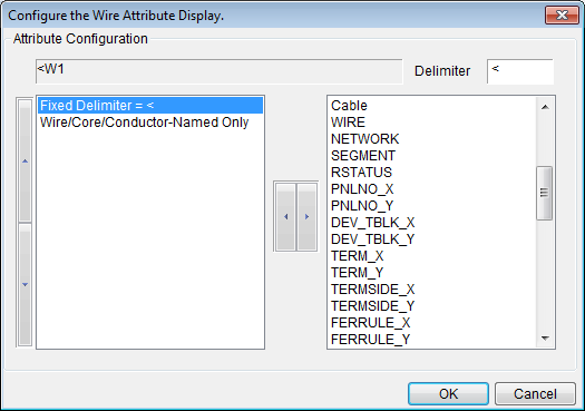
The fields of the two conductor reports, the from-to wire schedule (FromToWire) and the cable core(conductor) schedule (Corsch), are merged and added to the bottom of the list of specifically named items (listed above). You can add any of these fields to your conductor annotation for the attribute.
The conductor schedule fields that represent a termination are present in two sets of fields in each report; one suffixed _A and the other _B. For example PNLNO_A and PNLNO_B. In the attribute configuration dialog these same fields are listed, but with the suffix _X and _Y, e.g. PNLNO_X.
For a field name with the suffix _X, the wiring diagram generator will choose the _A or _B field that represents the destination termination, not the device or terminal strip that the wiring diagram represents.
For a field name with the suffix _Y, the wiring diagram generator will choose the _A or _B field that represents the source termination, the device or terminal strip that the wiring diagram represents.
Use Tag Alias
Use Tag Alias
Tick this check box to use Tag alias. More information about this feature can be found in the section below
Use an Arbitrary Reference for Labelling Connections
Cable [Panel]
Cable [Panel]
The destination panel name can be displayed with the cable name in the cable symbol on the cable line of a terminal strip. The destination panel name indicates the panel enclosing the termination at the other end of the conductor.
The panel name will be enclosed in brackets to the side of the cable name. The style of brackets can be specified in the "Brackets' box. By default this option is set to square brackets.
e.g. For a cable C12, that is connected at the far end of the cable to device K12 in panel MC2, the text on the cable line will read C12 [MC2].
If you do not want the destination panel name to appear on the cable line, clear the checkbox.
Use_ALT symbol for Cable with spares
If you tick the checkbox Use_ALT symbol for Cable with spares Wirediag will construct an alternate cable marker which will show the number of spare cores available for the each cable as shown in the figure below.
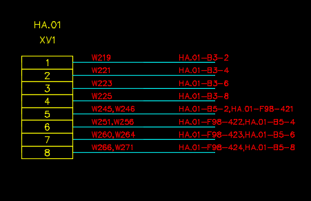
Show multiple conductors comma separated
If you tick the checkbox Show multiple conductors comma separated then Wirediag will draw only a single conductor line for each terminal, with internal wires and their destinations shown in comma separated lists, as shown below.
By default only internal wires are included in the comma separated conductors shown on a single line. External wires and cable cores/conductors remain shown on their own separate conductor lines.
If you tick the checkbox Include external wires then external wires will be included with the internal wires in the comma separated list on a single conductor line for each terminal.
If you tick the checkbox include cable cores/conductors then cable cores/conductors will be included with the internal wires in the comma separated list on a single conductor line for each terminal.
See also
Wiring Diagram Symbols and Attributes
Use an Arbitrary Reference for Labelling Connections
These settings can be found on the General tab page of the wiring diagram settings dialog.