Anchor Points: Inserting Sub Prototypes to a Master
Discussion
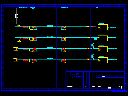
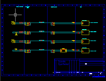
When using Protogen's relational system you can create a clone drawing from the combination of a Master Prototype and several Sub Prototypes inserted on to that Master. In this way you can create each individual clone with a varying graphic. E.g. for electrical circuits you could change the control scheme for each motor circuit by choosing an appropriate sub prototype.
| A clone with loop circuits choice A | A clone with loop circuits choice B. |
|---|---|
 |  |
Anchor Point Formulae
The insertion position of a sub prototype, on a master prototype, is controlled by an ANCHOR POINT. An anchor point is an AutoCAD text entity that contains a Protogen formula.
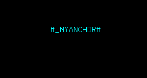
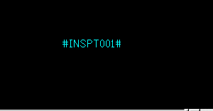
The Protogen formula for an anchor point must have one of two special field names. It can either begin with an underscore e.g. #_MYANCHOR# or use a name reserved by Protogen that starts with "INSPT" e.g. #INSPT001#. You can use either form of anchor point, which ever suits your project. Tip: The underscore version can be more "meaningful" however if linking to MS-ACCESS you may find that underscores do not import/ export correctly.
Anchor points are only valid on master prototypes. They are ignored on sub prototypes. I.e. you can not insert sub prototypes on to sub prototypes which in turn are to be inserted on to a master prototype.
| "Underscore" style Anchor Point | "INSPT" style Anchor Point |
|---|---|
 |  |
Anchor Points and the Master Database
When Protogen creates a master database, fields must be created for any anchor points found on the master prototype. These fields will have the name of the anchor points found.
In these fields you must enter the name of the SUB DBF which will supply the sub prototype name and its data.
Anchor Points in DBFs
In a sub database you must name the CLONE and the ANCHOR point when you wish to insert a sub prototype at an anchor point. This is done in the DRAWING (or SDRAWING) column of the sub database. You must separate the CLONE and ANCHOR with a '.' (Full stop / Period). If the Clone was named SHEET1 and the anchor was named _BORDER then the DRAWING or SDRAWING field should contain "SHEET1._BORDER"
SDRAWING and SPROTOTYPE fields in DBFs
These columns allow a row or record in the sub database to cause a sub prototype insertion AND also to be used as a SIMPLE Protogen database. An example of this would be the insertion of an instrument loop to a drawing via the SDRAWING and SPROTOTYPE fields and producing data sheets via the DRAWING and PROTOTYPE fields. If an SDRAWING field is created in a sub database then you must also create a SPROTOTYPE field.
Anchor Points and Protogen
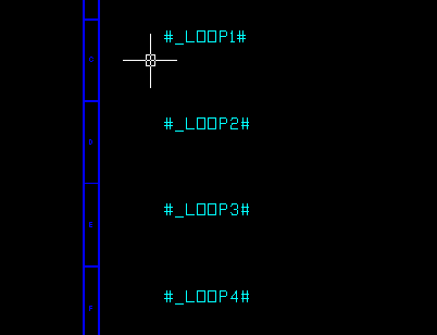
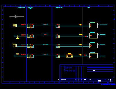
When Protogen recognizes one of the above anchor points it will record the insert point of the text entity for use during cloning. If you supply a sub database and name a sub prototype to be placed upon an anchor point (for any clone) then Protogen will insert the named sub prototype at that anchor point.
| Anchor Points on a Master Prototype (Before Cloning) | A loop circuit inserted at each Anchor point. |
|---|---|
 |  |
Positioning a sub prototype at (X, Y) from an anchor point
The situation may arise that you may need to insert a sub prototype NEAR an anchor and NOT ON IT. This could happen where you have a single anchor point and wish to place an array of sub prototypes at that anchor. The first insertion may be at the anchor and the others spaced evenly at +X,+Y relative to the point.
This situation MAY be handled by adding more anchor points. This MAY however clutter the master prototype and master DBF.
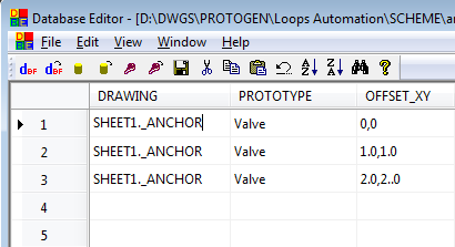
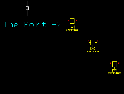
If you wish to insert a sub prototype NEAR an anchor, then you can add a field to your sub DBF with the special Protogen name OFFSET_XY. Inside this field the relative X and Y position from the anchor point may be entered. The X and Y must be comma separated. The X and y are in drawing units. For 3D drawings you can also include the Z coordinate in the OFFSET_XY column, comma separated from the X and Y values.
| 3 items inserted at 1 unit offsets from an Anchor point (DBF) | The resultant drawing. |
|---|---|
 |  |
