How to Place Screws
Procedure
-
If you want to place screws, choose the Place Screws entry from the Construction menu.
-
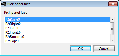
You will be asked to pick a mounting plate to place the screws on. You can either, pick an individual mounting plate or you can pick a panel frame. If you pick a panel frame, you will be presented with a list of plates that belong to that panel as shown below.
Choose one of the plates in the list.
-
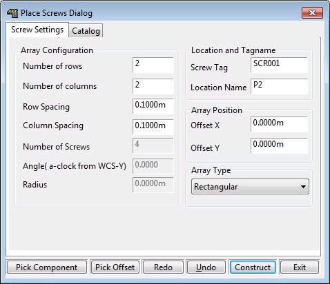
Once you have picked a plate you will be presented with the Place Screws Dialog shown below.
-
You can now configure the array of screws that you want to place.
Array Configuration
Number of rows The number of rows in the array of screws Number of columns The number of columns in the array of screws Row spacing The distance between the rows Column spacing The distance between the columns Number of screws The number of screws in a circular array Angle The angle anti-clockwise from the UCS Y axis of the first screw in a circular array Radius The radius of a circular array of screws -
Location and Tagname
Location The location of the screw Tagname The tagname of the screw Array Position
Offset X The X co-ordinate of the position of the first screw in the current UCS Offset Y The Y co-ordinate of the position of the first screw in the current UCS Array Type
Rectangular or Circular The type of screw array you want to place. Can be either rectangular or circular. -
You should now go to the catalog tab and choose the kind of screw you want to place. See using the catalog.
-
If you want to pick the position of the first screw in the array with the mouse then click on the Pick Offset button.
-
If you want to mount screws around an existing component on the model, click on the Pick Component button. Click on the component you want to place screws around. This component must be mounted on the plate you choose when starting the dialog. You will be asked to provide the offset values of the first screw in the array from the components lower left corner.
-
Once you are satisfied with the screw parameters, click the construct button. This will construct the array of screws and return you to the dialog.
-
If you want to undo the screws you have constructed, click on the Undo button, Your drawing will be restored to the state it was in, prior to you constructing the screws. This button is equivalent to the AutoCAD undo command.
-
You can also redo with the Redo button. This button is equivalent to the AutoCAD redo command.
-
To exit without constructing, click on the Exit button or close with the X in the corner of the window.