A guide to using Protogen...
To use Protogen effectively you must complete a number of engineering steps. There is more than one method which can be successfully used to make drawings with Protogen. We will describe the recommended method in this section.
The steps to using Protogen:
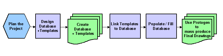
The steps described in words:
Planning
The planning of a Protogen project involves establishing the resources that are required as input, the role Protogen will play in processing these resources and the desired output from the project.
Output from the project will be drawings and reports. The drawings will typically be circuit and wiring diagrams and the reports will be rows and columns of circuit, connection and materials data.
The reports that contain materials data will invariably be loaded (with this data) from the input databases.
The output diagrams will invariably be clones of the input template diagrams.
Wiring diagrams, terminal strips, from-to connection data, warnings reports, cross reference reports, cable routing / filling reports are all by-products of the cloned circuit diagrams and materials reports.
Protogen's processing is essentially to merge textual data from the input databases with graphics representing whole circuits and parts of circuits to produce clone diagrams. These cloned diagrams may be used with Ebase to produce reports.
Design the System
The key input resources (template diagrams and the databases) can be derived by deconstructing the desired output of the project. E.g. The number of cables, tags and junction boxes required in the database can be derived from a sample loop diagram (possibly from a previous project). The template for the loop is almost a carbon copy of this sample loop diagram.
To specify the database and templates, make lists of the data necessary in reports and on the circuit diagrams and also list the types of circuit diagrams that you wish to create with the project.
Create the database with Protoedit
The Protoedit module can be used to create the databases for your project. The databases are defined by a file name and a set of columns, the width of these columns and the sequence or order of these columns.
We call the file / DBF table a database. We call each column in the DBF a "field". We call each row in the database a "record".
Create the templates with CAD
A template diagram or prototype can appear to be all of or part of a complete output diagram. An example of a "template part" of the complete output diagram would be a title block, inserted on the diagram by Protogen and loaded with title-block data by Protogen. To create a template diagram you essentially draw the diagram (or part of the diagram) in CAD. To complete a template you must add "field links" to the diagram. "Field links" connect textual (and graphical) items on the template diagrams, to the Protogen databases.
Create the links from templates to database with Protoedit
With Protoedit you can select a database to use and then connect textual (and graphical) items on the template diagrams to that database.
Linking templates to a database.
Populate the database
Protogen provides a browse editor which allows you to enter database data which will eventually be placed on diagrams and reports. This involves simply typing in your data to the DBF tables of your Protogen project.
Some fields require special information and these typically have assistant functions for selecting this information.
Populating the database and special fields.
Create the drawings
When the database is populated you can produce the drawings, defined by the database, from within Protogen