IO Card Symbol Changes
You can change the "look" and size of the symbols used as building blocks on the IO cards. These symbols are all standard device blocks as used in a switch or circuit breaker inside Elecdes. The symbols are all stored in the IMP_PLC or MET_PLC directory. You can edit all of these blocks if you wish.
Each symbol represents one of the following four block types.
PLC tag block
This is the "Header" block of the card and is used for holding bill of materials data. It must be named HIPLCTAG.DWG or VIPLCTAG.DWG. It should not have any terminals.
PLC base block
This is the "Last" block of the card and is used for aesthetic reasons only. It must be named HIPLC_BASE.DWG or VIPLC_BASE.DWG. It should not have any terminals.
PLC continuation blocks
These are the "splitting" blocks of the card and are used for aesthetic reasons only. They must be named HIPLC_CONT.DWG or VIPLC_CONT.DWG for continuations placed on the top/left of a card and HIPLC_CONTB.DWG or VIPLC_CONTB.DWG for continuations placed on the right/lower side. They should not have any terminals. You can edit these blocks if you wish.
PLC IO blocks
You can edit these blocks if you wish.
The IO block file names are all formatted: HIPLC<code><M>.DWG or VIPLC<code><M>.DWG.
The optional M (mirror) character tells the wizard that the symbol is for cards on the right side or lower side of the construction. Cards on the top or the left do not have an M.
The <code> following xxPLC tells the wizard of the type of IO channel this symbol represents:
-
DO = digital output
-
DI = digital input
-
AO = analog output
-
AI = analog input
-
PWR = an external supply line
-
COM = a common leading back to the CARD from a number of Io's
-
GND = an earth.
-
The number in the code represents the number of terminals on the symbols 1,2,3.
Examples:
VIPLCDO2.DWG Vertical card, digital output, 2 terminals, placed on the left side of the construction (wiring will be on the right).
HIPLCCOM1M.DWG Horizontal card, common line connection, 1 terminal, placed on the LOWER side of the construction (wiring will be on the top)
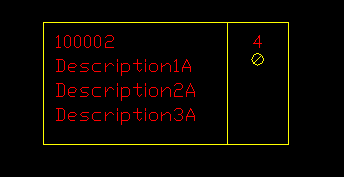
An Inserted IO block
Special considerations for IO Card Blocks
IO Card symbols have some special features that must be noted when customising.
They all have a "bounding box" surrounding their terminals. This box is used for SIZE calculation when stacking the symbols alongside each other to make a card. If you alter the size of the box you will alter the spacing required for that channel on the card.
The insert point must be aligned with the terminals of the card and NOT the bounding box. This is to ensure all Elecdes connection rules will work. In the following description a bracketed position, e.g. [lower], indicates the options for a vertical card symbol. If the Block is an M block, then the insert point will be on the left [top] quadrant of the leftmost [topmost] terminal on the left [top] side of the device. If it is not an M block, then the insert point will be at the horizontal [vertical] distance toward the left [top] that is set by the LENGTH attribute FROM the rightmost [lower] quadrant of the top [leftmost] terminal on the symbol.
The Tag blocks have a PLC_RACK and PLC_SLOT attribute, which exist on no other symbols.
The IO blocks have a PLC_ADDR attribute and PLC_DESC1, PLC_DESC3, PLC_DESC3 attributes, which exist on no other symbols. The PLC_ADDR attribute will contain the address of the IO channel and the three descriptions can be used for the function of that channel. In the example shown above, the descriptions have been set and the address is 100002.
The BUSW codes must be set correctly for symbols with multiple terminals.
For more information on modifying Elecdes device symbols: