Reference, Indicator and Operator Symbols
General
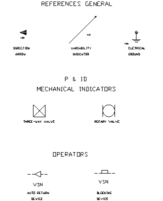
Reference and Indicator Symbols are provided to add drawing clarity. For electrical schematic diagrams, general indicators and operational indicators are provided. For instrument loop diagrams some sample mechanical symbols are provided.
Examples:
-
General indicators: Arrowheads, rotation indicators etc.
-
Operators: Switch operator functions: Push, pull, turn, float, fluid, etc.
-
P&ID Mechanical: General mechanical symbols found on P&IDs. These may be used on your loop diagrams for showing mechanical components related to loops. Contains pumps, valves, taps etc.
Symbol File names
The file/block names are user defined. They can have any file name that is not recognised as an Elecdes component symbol.
Elecdes Symbol Naming Conventions
Directory
The files for these symbols are all found in the following directories:
-
Reference and Indicator symbols: <EDS >\IMP_RFIN and <EDS >\MET_RFIN (for metric users);
Location on the Menu
The icon menus for reference, indicator and operator symbols can be found on the menu. The symbols are divided into categories, listed below. Each category displays an ICON menu of symbols.
-
Operator symbols
-
Reference and Indicator symbols
-
Mechanical Reference symbols
Insertion Procedure
Attributes of Reference and Indicator Symbols
The Reference and Indicator symbols in general have no attributes. A single attribute may be placed on a reference or indicator symbol. This attribute would be used for drawing annotation only and will not be used in reporting. None of the supplied symbols in this category have an attribute.
Customisation of Reference and Indicator Symbols
For information about adding and customising Reference and Indicator symbols and their menu entries see Symbol Modification.