How to Configure Mapping for DWG to DGN Conversion
Fundamentals
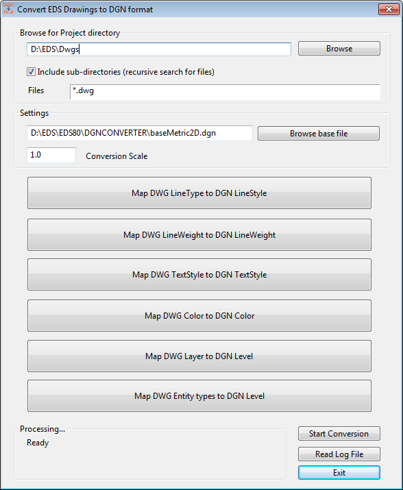
The DGN Converter uses mapping rules to specify how DWG entities and properties are converted to DGN entities and properties, for example which DGN level to use for each drawing layer. The DGN Converter window has a button to open an editor for each available mapping. The actual mapping rules are stored in separate DBF files in the <EDS>\DGNConverter directory.
Map DWG Line Type to DGN Line Style
You can map each DWG line type to a DGN line style. In the default mapping file, common DWG line types are mapped to their closest suitable line styles in DGN. You can change these mappings to suit your individual requirements.
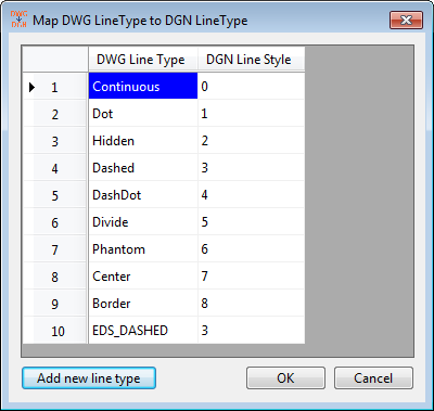
If you use DWG line types that are not currently listed, you can add a new line type to line style mapping rule by pressing "Add new line type".
Map DWG Line Weight to DGN Line Weight
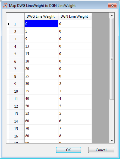
You can map each DWG line weight to a DGN line weight. In the default mapping file, all of the possible DWG line weights are mapped to their closest suitable Line weight values in DGN. You can change these mappings to suit your individual requirements.
The DWG Line Weight column contains the entire set of line weights that are visible to EDS so you cannot add new entries to the line weight table, you can only change the DGN line weight that each is mapped to.
Map DWG Text Style to DGN Text Style
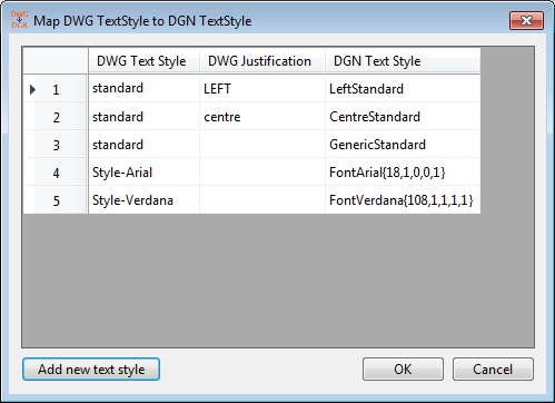
You can map each DWG text style and optionally a specific justification to a DGN text style. The DGN text style to be used must be present in the base DGN file. If the style does not exist in the base file, then the individual properties of the DWG text style will be set to the DGN text without setting a text "style". The same occurs when there is no mapping for a particular DWG text style.
This fall-back for a missing text style mapping does not set all of the properties and does not set a DGN Font ID. To create DGN text properly without a text style, provide a suitable mapping as described below.
In each text style mapping the DWG Justification field is optional. If the mapping specifies a DWG justification, then only DWG text with the specified style and justification will be mapped to the specified DGN text style. If the DWG justification field is left empty then DWG text with the specified style and any justification will be mapped to the specified DGN text style. A mapping that specifies the correct DWG justification will be used in preference to a mapping that does not specify the justification.
In the following example, DWG text using style "Standard" and Left justification would be mapped to DGN text style "LeftStandard" by the first mapping. DWG text using style "Standard" and Right justification would be mapped to DGN text style "GenericStandard" by the third mapping, and DWG text using style "TitleText" and any justification would be reproduced by applying the DWG text properties to the DGN text without using a DGN text style.
In the default mapping file there are no text style mappings, so all text is reproduced by applying DWG text properties to the DGN text. The supplied metric and imperial base DGN files do not contain any text styles.
You can add text style mappings by pressing "Add new text style" and entering the appropriate DWG text style name, DWG justification and desired DGN text style.
Map DWG Text Style to DGN Text with a Font ID and Parameters but no Text Style
DGN files can contain text without a text style and instead with individually set format parameters.
The DGN Converter allows you to create DGN text with no text style from a AutoCAD text with a text style by using a map entry that specifies the text properties, like those shown in records 4 and 5 in the figure above. This entry can be used to set the text properties: font ID, bold, underline, over-line and italics. The general format for the entry is ENTRY NAME { FONTID, BOLD, UNDERLINE, OVERLINE, ITALICS } where each of the parameter must be placed within the curly brackets separated by a comma. The table below describes each of these parameters.
| Parameter | Usage |
| Entry name | You can use any suitable entry name for your reference like Arial, Default etc. The entry name is for your reference only and has no affect on the output text. |
| Opening curly bracket | All of the text control parameters must be placed within the curly brackets and must be separated by commas. |
| Font ID number | You must specify the Font ID number from your MicroStation installation. The text is created with this font in the exported DGN file. |
| Bold (On/Off) | Must be set to 1 to create bold text otherwise set it to 0. |
| Underline (On/Off) | Must be set to 1 to create underlined text otherwise set it to 0. |
| Over line (On/Off) | Must be set to 1 to create over-lined text otherwise set it to 0. |
| Italics (On/Off) | Must be set to 1 to create italic text otherwise set to it 0. |
| Closing curly bracket | The closing bracket marks the end of the text setting. |
In the example above, DWG text using a style named "Style-Arial" would be mapped (via a mapping named "FontArial") to DGN text with font ID 18, is bold, is not underlined or overlined, and is italicised.
NOTE:
This type of text mapping is useful when converting DWG files that were originally exported to DWG format by MicroStation. If the original DGN files contained text with no text style then, when exported by MicroStation to DWG format, MicroStation will have created one or more text styles in the DWG files that were not present in the original DGN files. These text styles are named with a prefix of "Style-" followed by the font name, e.g. text in the DGN file with no text style and font set to Arial will be set to use a new text style named "Style-Arial" when exported to DWG format by MicroStation. This new text style does not exist in the DGN file. To maintain the new DGN in the style of the original DGN, without extra text styles, you can map the DWG text styles that were automatically created by MicroStation back to DGN text with directly set properties.
Character codes with %% format
The DGN Converter will export special character codes in DWG text to DGN text without any changes. However some of these characters are only supported by the True Type fonts. You must set an appropriate text style in the DGN file to correctly see text containing special character codes. Special character codes that may require a True Type font are listed here.
| %%d | Draws a degrees symbol (°). |
| %%p | Draws a plus/minus tolerance symbol (±). |
| %%c | Draws a circle diameter dimensioning symbol (Ø). |
| %%% | Draws a single percent sign (%). |
Map DWG Color to DGN Color
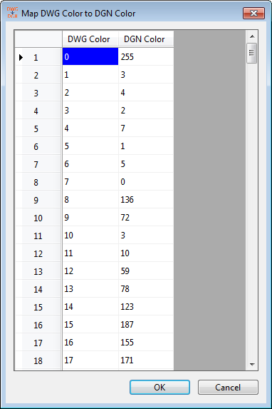
You can map each DWG color, specified as an AutoCAD Color Index (ACI), to a DGN color. In the default mapping file, all of the possible DWG colors are mapped to their closest suitable color values in DGN. You can change these mappings to suit your individual requirements.
The DWG Color column contains the entire set of AutoCAD color indices that are visible to EDS, so you cannot add new entries to the color mapping table, you can only change the DGN color number that each is mapped to.
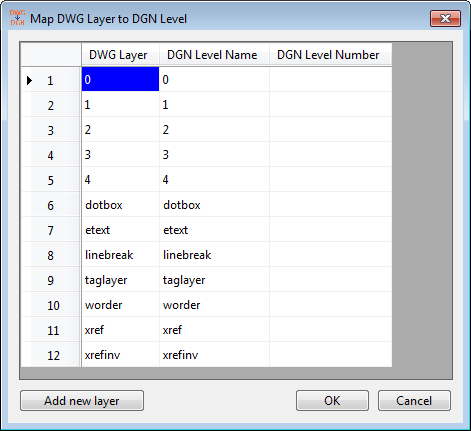
Map DWG Layer to DGN Level
You can map each DWG layer to a DGN level either by name or by number:
-
Mapping a DWG layer to a DGN level by name.
A named level can be created in the DGN file for each specified mapping, if it does not already exist in the base DGN file. The DGN level name does not need to be the same as the DWG layer name.
e.g. If DWG layer "xref" is mapped to DGN level "xref" then a level named "xref" will be created in the DGN file. All the properties of DWG layer "xref" will be copied into DGN level "xref". In cases the DWG layer "xref" is not found, the properties will not be set of DGN level "xref" and you should expect their DGN defaults.
-
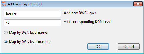
Mapping a DWG layer to a DGN level by number.
Mapping by number means that you can map a DWG layer to a DGN level based on its level number.
Note that you can have a level named "4" and also a different level which is number 4. The level number is different from the level name. You can specify a mapping rule to map to a level which occurs at a specific number in DGN file.
If you map to a level by number then that numbered level must exist in the base DGN file. If the specified level number is not available then all the entities placed mapped to this numbered level will go to the "default" or 0 level in the DGN file.
All the entities which are on a DWG layer will be placed on the mapped DGN level, unless there is a mapping for that specific entity type - see Map DWG Entity to DGN Level, below. Entity to level mapping overrides layer to level mapping.
You can specify a new DWG layer to DGN level mapping rule. Note that you can only map to a DGN level either by name or by number. Having values in both columns in the mapping file is an error and you will be notified by the system if it happens. Similarly, you must specify a mapping in at least one column and you cannot leave both fields empty.
Map DWG Entity to DGN Level
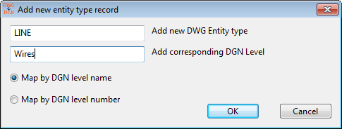
You can map DWG entities based on their entity type to a DGN level. For example, you can specify if you want all LINE entities to be placed on a DGN level named "Wires" or if you want all INSERT (inserted block) entities to be placed on a DGN level numbered 3.
All of the named levels mentioned in the DWG entity to DGN level map are created before processing the drawing entities, regardless of whether or not there were entities to map to those levels.
If the levels specified in this entity to level map do not also exist in the layer to level map then the created DGN level will be turned off. The mapped levels have no DWG layer from which to copy their properties. You can turn them on in the final DGN to view the entities which now belong to the created levels.
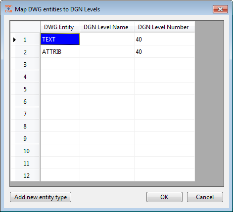
You can specify a new rule for mapping DWG entities to DGN levels. The same restrictions that are discussed above in DWG layer to DGN level mapping apply to the entity to level mapping: you must specify only one of either the level name or level number for each mapping.
Note: DWG entity to DGN level mapping overrides DWG layer to DGN level mapping rules.
Consider this scenario: There are LINEs and CIRCLEs on layer 4 in the DWG file. According to DWG layer to DGN level mapping rules everything on layer 4 should go to level named "4" but the DWG entity to DGN level mapping states that all LINE entities should go to DGN level named "Wires". In the converted DGN files, the lines will be created on level "Wires" and the circles will be created on level "4".