How to Configure the Symbol Spacing
General
You can configure the spacing of the symbols in the cross-reference list.
Procedure
-
Go to the Options tab page.
-
Choose the type of settings for which you wish to configure the spacing. Either Normal Settings or NONC or BOM Table settings.

-
There are five spacing settings that you can adjust. These are shown below:
| Setting | Description |
|---|---|
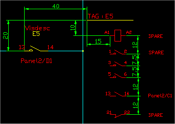
| Coil to Header X,Y | The offset of the header of the reference list from the coil symbol on the schematic. |
| Header to First Item X,Y | The offset of the first item in the reference list from the reference list header in drawing units. |
| Spacing:Normal | The spacing between the components in the reference list in drawing units. |
| Additional Per Phase |
The additional amount of spacing to add for each phase above one. E.g. added twice for three phase symbols. The phases for a symbol is determined from the symbol name. i.e. HI3PCOS is a 3 phase symbol. This spacing is also used in the BOM/XREF table form of cross referencing if you have selected that system of cross referencing. |
| Symbol Scale | The scale used for the symbols in the reference list. |