How to Place Components from a List
General
You can now create a list of devices, instruments and panels in DBF format and Paneldes will import and construct these on your model. To enable construction you must supply spatial position information, tagging information and also catalog information, which includes (by lookup) the dimensions and shape for construction.
Procedure
-
Select Place Components from List from the Construction menu.
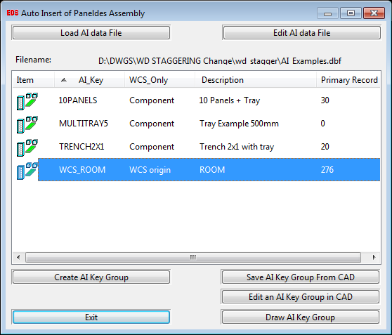
Paneldes will display the Auto Insert of Paneldes Assembly dialog which is used for various Auto Insert functions like loading, creating, editing and saving your project AI file.
-
Firstly, you will need to choose your data file by clicking the button. You will be presented with a file opening dialog allowing you to choose and load your AI data file. If you don't have an existing AI file you can simply type the desired name for your AI data file and Paneldes will create it for you. After the successful load your AI data file name will appear on the dialog like this
 . If the AI data file already contains some AI groups then they will appear in the AI group list like shown below.
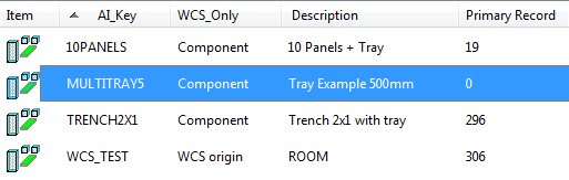
Once you have chosen an AI data file you can create an empty AI key by clicking the button. You will be presented with a dialog where you can set the AI Key name, and it's description.
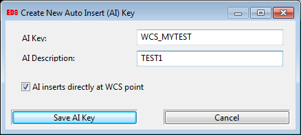
By default, Paneldes inserts an AI group at the base point of the selected primary object. You can also choose the AI key to be inserted in WCS by ticking the checkbox AI inserts directly at WCS point. After filling in the name and description, you can save your new AI key by clicking the button, which will add an empty AI Key to the AI group list and your data file.
Note: Paneldes will show you a warning if the AI Key already exists in the data file.
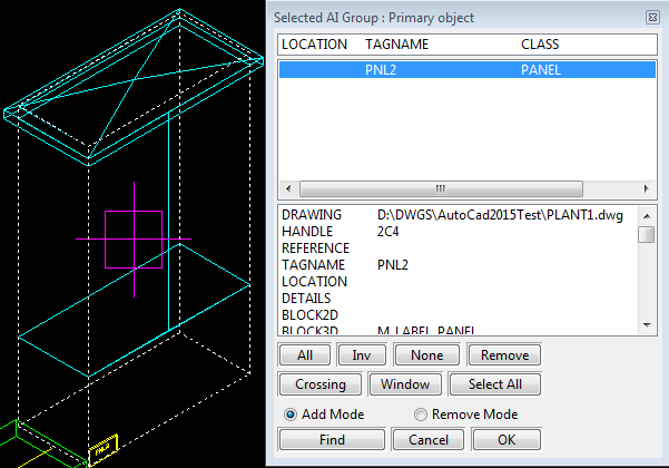
Once the AI key has been created, you can add the objects directly from CAD into your AI key group by selecting an AI Key from the list and clicking on .
-
If your AI key is chosen to be inserted at the object base point then Paneldes will first ask you to choose a primary object that is to be the Primary Positional Reference Object for the selected AI Key Group. A warning will be shown if you do not choose any object or choose more than one object.
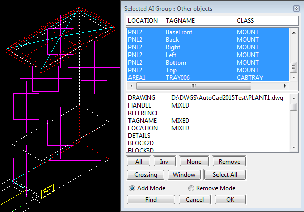
After choosing the primary objects you can pick Other Paneldes Objects to include in this Key AI Group.
If your AI key is chosen to be inserted at the WCS point then Paneldes will allow you to choose anything from the list of all of the objects on the drawing like shown below.
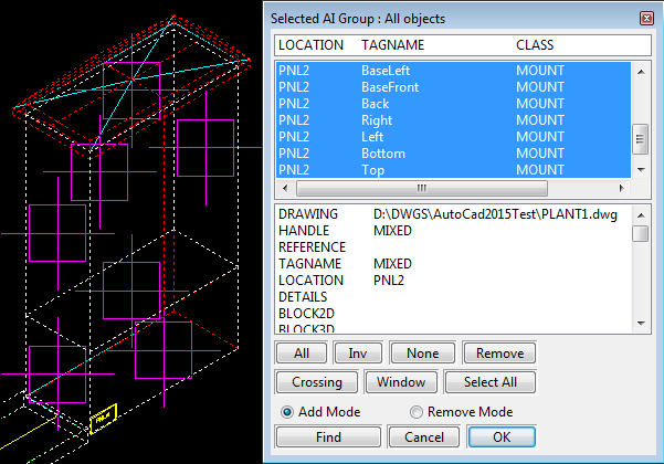
After selecting entities from drawing you can press to add all of the selected entities to the currently selected AI Key.
-
You can draw your AI groups in your CAD by clicking the button. If the AI group was chosen to be inserted at the WCS point then the group will be inserted in WCS co-ordinates, otherwise it will be inserted in the base point of the primary positional reference object (which was chosen while creating the AI group).
-
Choose the base point for the insertion.
The chosen base point will only be used for components with relative position values (the position includes "@").
If you have only used absolute position values, you can enter (0,0,0) for this point the value you enter will not be used by the program.
File Structure
Paneldes provides a template file named templateAI.dbf that is used for all of the auto insert functions and should be located in the RTEMPLATE folder of your installation. The file contains the following columns that are used by AI functions.
| KEY | A key used for grouping various objects within an AI group (i.e. All the components in an AI group will have the same key.) |
| VISDESC | Visual description of the component (e.g Cap screws for brackets). |
| CLASS | Paneldes class of component (e.g. DEVICE / PANEL). |
| TAGNAME | The tagname of the component. |
| LOCATION | PNLNO tag for devices / LOCATION tag for panels. |
| MFG | Manufacturer's numeric code. (E.g. 1 = Merlin Gerin). |
| CATNO | Manufacturer's catalog number. |
| NAME_FORCE | If you want the entity to have a new name every time even if its LOCATION is changed then put "NOLOCATION" in the NAME_FORCE column. This will make sure that the entity (e.g. device, instrument etc.) is always given a new name. |
| POWER | A number representing the power rating for this cable. Used by Paneldes to separate cables with different power ratings during cable routing. Must match the power rating of the raceway intended to carry the cable. 0 (zero) is general and can be placed in any raceway. |
| EXTENDABLE | If the primary object is a raceway length segment (e.g. a straight trench) then it can be stretched to the desired length if it is marked with "Y" in the EXTENDABLE column. Other length segments of any type that are also marked as EXTENDABLE will also be stretched by the distance that the primary segment is stretched Note that the same amount of additional length is added to each extendable segment. They are not necessarily made the same final length. For example, when creating an AI group for a trench you can choose to mark the entries for cable tray or conduit in the trench so that they will be stretched by the same amount as the trench when the trench is inserted. |
| REPEAT_LEN | If the primary object is a raceway length segment (e.g. a straight trench) then any entities that have a distance in the REPEAT_LEN column will be repeated for each interval that the length of the primary object is longer than a multiple of the repeat length beyond the original position of the entity For example, when creating an AI group for a trench you can choose to repeat a wall bracket every 2 meters (enter "2m" in the REPEAT_LEN column). If the trench is stretched so that it is 6 meters long and the first bracket is 1 meter down the trench, then an additional wall bracket will be inserted at 3 meters and 5 meters down the trench. |
| NORTH |
Y value of the position of the component, e.g. "20ft". OR relative Y value of the position of the component, e.g. "@20ft". |
| EAST |
X value of the position of the component, e.g. "10ft". OR relative X value of the position of the component, e.g. "@10ft". |
| ELEVATION |
Z value of the position of the component, e.g. "30ft". OR relative Z value of the position of the component, e.g. "@30ft". |
| XVECT_X | The X axis of the coordinate system of the entity. |
| XVECT_Y | |
| XVECT_Z | |
| YVECT_X | The Y axis of the coordinate system of the entity. |
| YVECT_Y | |
| YVECT_Z | |
| STD_PLATES | If this value is set to "FALSE" or "NO" then the standard plates of automatically inserted panel components will be omitted. Only the panel frame will be inserted. |
| HEIGHT | Parametric height for components with a rectangular cross-section. e.g. 230mm Used by Paneldes to construct the physical model. |
| WIDTH | Parametric width for components with a rectangular cross-section. e.g. 100mm Used by Paneldes to construct the physical model. |
| RADIUS | Parametric radius for components with a circular cross-section. e.g. 150mm Used by Paneldes to construct the physical model. |
| LENGTH | Parametric depth or length for components with a rectangular or circular cross-section. e.g. 230mm Used by Paneldes to construct the physical model. |
| BENDRADIUS | Parametric radius for bends in raceway, e.g. 200mm. Used by Paneldes to construct the physical model. |
| CNRANGLE | Parametric inside corner angle for bends in raceway, i.e. corners or risers. Inside angle means it will be 180° - deviation from straight. "150" for a corner that deviates 30° from a straight line. "150" for an inside riser that rises 30° up from a straight line. "210" for an outside riser that drops 30° down from a straight line. "30" for a tee that branches 30° to the left. "-30" for a tee that branches 30° to the right. Used by Paneldes to construct the physical model. |
| SECHEIGHT | Additional parametric height for some segments of raceway, e.g. 45mm. Used by Paneldes to construct the physical model. |
| SECWIDTH | Additional parametric width for some segments of raceway, e.g. 45mm. Used by Paneldes to construct the physical model. |
| PROTRUDE | Parametric protrusion of the front of the component through a mounting plate. E.g. 20mm. Used by Paneldes to construct the physical model. |
| VERTICAL | Set to "TRUE" or "YES" if the component should be oriented vertically. |
| POSITION |
Component position specified in one column with comma separate values. Absolute 3D position, X,Y,Z with units, e.g. "10ft, 20ft, 30ft". Or relative 3D position, @X,Y,Z with units, e.g. "@10ft,20ft,30ft". |
| NTH_FRONT |
The angle of the component from North. If the list is processed automatically from a catalog spec, see below, specify the angle from the front of the originally inserted component. |
Notes:
Items, which cannot be resolved from the catalogs, will not be inserted.
The data from the Elecdes BOM is very similar to the above and can be "massaged" into this format.
The DBF file may have any file name.
Always use relative position if this list is inserted as extra components from the catalog see below.
The separate position columns, NORTH, EAST and ELEVATION, will be used only if the POSITION column is left empty.
Automatic insertion of extra components from catalog
When you insert a component, Paneldes checks the chosen catalog specification for a link to one of these insertable component lists.
The catalog specification should have the following extra columns:
| AI_FILE |
Name of an insertable component list, as described above. The file should be located in the same folder as the catalog file: MET_CAT or IMP_CAT. |
| AI_KEY |
Optional key name to select components from the insertable component list. This value is checked against the KEY of each record in the component list, see above. This key can be any user defined text name e.g. "MYKEY" |
The POSITION or NORTH, EAST and ELEVATION values in the insertable component list should always be relative, with "@" prefix.
The NTH_FRONT value should specify the desired angle relative to the front of the originally inserted component.
If the file is found, then Paneldes will insert all of the components from the file that have a KEY value matching the AI_KEY value. The insertion base point and orientation, of the list based components, is the insertion point and orientation of the original component you were inserting.
Auto insert dialog buttons and columns:
Item
Displays an icon for each AI group in your AI data file.
AI_Key
Displays the name of the AI Key for an AI group.
WCS_Only
If the AI group uses the WCS coordinates for insertion then this column will display WCS_origin otherwise it will show Component in it.
Description
Displays the description for your AI key.
Primary record
Displays the record number of the primary record of the AI group in your data file. e.g. if your AI group starts from record number 50 then it will display the number 50 inside this column.
Load AI data file
Opens a file opening dialog allowing you to choose and load your AI data file.
Edit AI data file
Opens your AI file in Database Editor where you can manually edit the dbf file and save it.
Create AI key group
Creates new AI key with user specified AI Key name and description. Also allows you to choose to insert the AI Key group directly at the WCS point.
Save AI key group From CAD
Allows you to select the objects from your drawing and add to the the selected AI key.
Edit AI key group From CAD
Allows you to edit your existing AI groups. When you choose to edit an AI group, Paneldes will draw the selected AI group inside the drawing where you could make all the necessary changes. After finishing the changes you can re-save the AI group using the button and re-selecting your updated group.
Draw AI key group
Draws the selected AI group onto your drawing. The group will be inserted directly in the WCS if it was selected at the time of creating the group.