Interface Overview
The Instrument Manager program has a menu and toolbar at the top of the main window that are fixed in place. Each open project has its own window within the main window. The project windows display the data from the project database in different modes to suit different editing purposes: list, edit and connection view.
Main Menu
Instrument Manger has pull-down menus along the top of the window. Some data importing and reporting functions are only available from the File menu. Configuration options can be found either on the View or Tools menus. The Edit menu contains the same functions as the pop-up menu for the currently selected item in the category tree.
Toolbar
See Toolbar commands.

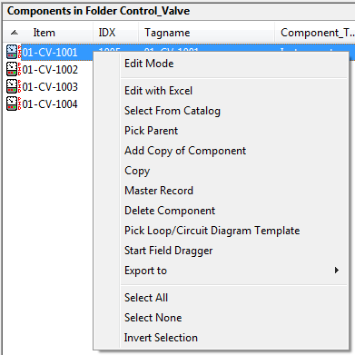
Pop-up Menu
Most items in the Instrument Manager windows have a pop-up menu. The pop-up menu has editing options specific to the item for which it is displayed.
To display the pop-up menu for an item, move the mouse over the item and click the right mouse button.
Navigate to Components and Diagrams
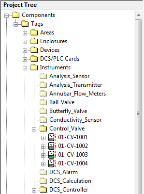
Category Tree
The category tree shows a summary of all of the data stored within an Instrument Manager project. The category tree is always shown on the left side of a project window. Each item in the project database is summarised by displaying its "name" in the category tree. For example, the "name" would be the tag for an instrument or the file name for a data sheet.
The entries in the tree are structured such that related entries are grouped together under categories. You can expand and collapse categories as necessary to view or hide the entries within them.
Components contained within other components, for example instruments in an area, display "links" under their container component. Thus an instrument may appear in more than one place in the tree: once in the appropriate instrument category, and also as a link under the area into which it has been placed.
Data Lists
The two data lists show more details about the item currently selected in the tree. The two data lists are always shown one above the other on the right side of a project window.
If a category is selected in the tree, then the top list will show the items contained in that category. The bottom list will show the ratings record for each component.
If a component is selected in the tree then the top list will show the details of that component. The bottom list will show the components contained within the selected component, for example terminal strips in a selected enclosure.
Both data lists can switch between a list and an editor. To change the view, from the View menu choose either List View or Edit View. You can also double-click the left mouse button in list view to switch to edit view.
List View and Edit View
List view and edit view are used to view, add, delete and edit components. For both views, the project window is divided into two main areas of control: a category tree on the left and two data lists on the right. Switching between list and edit view changes only the data lists. The category tree remains the same. The divider bars between the trees and lists can be moved to resize your views.
List View
Initially the view will contain lists of components or component data. List view provides an interface for operating on each entry as a whole entity. In the list view, you can select multiple components to edit simultaneously. The pop-up menu in the list view generally has options to add, copy, delete and edit components.
Edit View
The list view can be switched to a row and column editor. This shows the same rows and columns as the list view; however you can type data directly into the cells.
A dragged selection in the edit view will select multiple cells, but does not select whole components. This cell selection is provided to edit the individual cells of data of the components.
In the edit view the pop-up menu options relate only to editing the data within the selected cells. For example: cut, copy, paste and increment. You can paste data from other programs into the edit view.
From the edit view you can display a Form Edit window. This shows the columns from the component record(s) in a list vertically down the screen, meaning you can see and edit more of your component data in one window. You can modify the data from multiple records with one operation.
Filtering and Sorting the List and Edit Views
The list and edit views can be quickly filtered and/or sorted, allowing you to reduce the volume of components in the list to a manageable quantity.
Managing large numbers of components
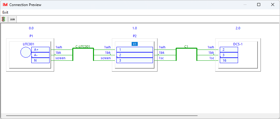
Connection Preview
The Connection Preview window is a separate "floating" window that shows a graphical preview of the connections associated with the component or conductor that is currently selected in the tree or list view. This is the same graphical preview that is shown in the bottom pane of Connection View, except the Connection Preview window remains visible no matter which view is in use.
The Connection Preview window is separate from the main window of Instrument Manager and can be re-sized and moved, even to a second monitor. It remains on top of Instrument Manager if placed in the same area.
Choose the "View" menu then choose "Preview Window".
Connection View
Connection view is used to connect components with cables and wires. The display in connection view is divided into four panes. The top three panes display category trees for equipment, conductors and equipment again, in that order. The bottom pane displays a preview of the connections associated with the component or conductor that is currently selected in the trees above. The divider bars between the panes can be moved to resize your views.
The connection view is designed so that you can use drag and drop operations to make connections between equipment and conductors. You can drag equipment from one of the outer trees onto cables or wires in the centre tree to make a connection. The drag operation can also be done from the conductors to the equipment.
Floating List Window
You can show a modeless floating window that can show a filtered list of multiple components.
Using this window you can view and act on components (by using the Drag-Drop operations or the Pop-up Menu) that otherwise may require repetitive scrolling or switching between different components.
To open the floating list window, click on View > Floating List Window.
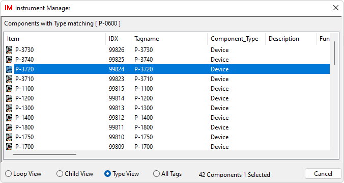
There are four different list views available in the Floating List Window:
| View | Description |
| Loop View | Lists all of the components in the project that have the same numeric suffix in their tagname as the component selected in the list or tree in the main window. |
| Child View | Lists all of the child components of the component selected in the list or tree in the main window. |
| Type View | Lists all of the components in the project that have the same component type as the component selected in the list or tree in the main window. |
| All Tags | Lists all of the components in the project. |
Data Importing and Reporting Wizards
The functions for importing data into the project database and reporting data from the project database use a wizard-style interface that offers choices, in sequence, to configure the operation. The wizard is displayed when the function is run. You can step forwards and backwards through the wizard pages to alter the chosen options. At the end you click the [Finish] button and the function runs with your chosen options.
See also:
Navigate to Components and Diagrams