How to Insert a Multi-Terminal Device Symbol
Fundamentals
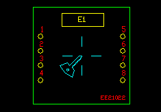
Multi-Terminal Device, or MTD, symbols may be inserted anywhere on a schematic drawing.
MTD symbols can be inserted into and break lines like standard symbols. MTD symbols only insert in one orientation.
MTD symbols represent devices. When MTD symbols are inserted they reference the CATD??.DBF catalog file for data.
An MTD symbol is represented by more than one block on the drawing. These blocks are associated together in a GROUP on the drawing so they can be treated as a single entity.
Procedure
-
Pick from the menu or choose one from an icon menu.
-
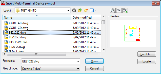
If the icon menu or pull down menu entry selected does not contain a pre-defined MTD symbol name, a list of the file names of the symbols that have been stored within the MTD subdirectory is displayed. Select the file name for the MTD device that you wish to insert.
-
Elecdes will break any lines that pass into or through the boundary of the terminals of the MTD symbol. The line break will occur at the terminal boundary. This may be different to the boundary of the graphical part of the MTD, which determines the size of the soft snap box.
-
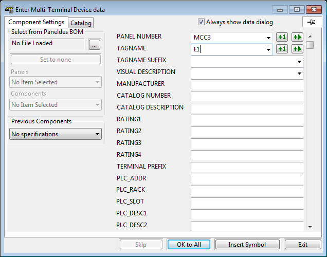
The Elecdes Component Dialog will be displayed, as in the standard insertion procedure. You should enter the name, location and any other data that needs to be manually entered (e.g. visible description or function) into the edit boxes to the right.
Refer to the section How to Insert Symbols for more information on entering and selecting data for a component.
-
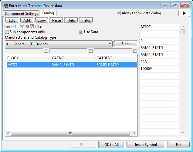
On the catalog tab page of the component insert dialog, Elecdes provides a special filter for MTD catalog entries (as opposed to normal device components).
The BLOCK that you are inserting or updating is normally used as a filter for the component listing in the catalog. For all MTD symbols the device block symbol is the MTD tag block, either HIMTDT.DWG or VIMTDT.DWG. This would normally imply that a catalog entry of "MTDT" would match all of the MTD symbols. To allow for correct filtering of the catalog component list, the original file name of the MTD symbol may be appended to the generic block name "MTDT" (following a comma) as follows:
-
Any catalog entries that do not have the original block name following the generic MTDT will also be listed (at the bottom of the list). This assists in using any catalog entries made with older versions of EDS
-
-
When you are satisfied with the data in the Component Dialog, click .
-
You must then select the device insert point.
A "Soft Snap" cursor box is provided. This displays a surrounding box representing the size of the MTD symbol to insert. Elecdes will "snap" the designated insert point of the MTD symbol to any line segment that it detects under the cursor. The insertion point is set when the MTD symbol is created.
-
The data selected will be placed in the attributes of the MTD tag symbol and terminal symbols, then the MTD symbol will be inserted. Once inserted, the nested block will be exploded to leave a tag, terminals and graphical elements blocks on the drawing. All of these blocks are associated together in a GROUP so they can be treated as a single entity in the drawing.
-
If you need to modify the individual elements of an MTD that is inserted in a drawing you will need to turn group selection off. Press Ctrl-Shift-A to turn group selection off and press Ctrl-Shift-A to turn group selection on again.